Driving a 3D Lunar Lander Model with ARM and Ada
by Pat Rogers –
One of the interesting aspects of developing software for a bare-board target is that displaying complex application-created information typically requires more than the target board can handle. Although some boards do have amazing graphics capabilities, in some cases you need to have the application on the target interact with applications on the host. This can be due to the existence of special applications that run only (or already) on the host, in particular.
For example, I recently created an Ada driver for a 9-DOF inertial measurement unit (IMU) purchased from AdaFruit. This IMU device takes accelerometer, magnetometer, and gyroscope data inputs and produces fused values indicating the absolute orientation of the sensor in 3D space. It is sensor-fusion on a chip (strictly, a System in Package, or SiP), obviating the need to write your own sensor fusion code. You simply configure the sensor to provide the data in the format desired and then read the Euler angles, quaternions, or vectors at the rate you require. I plan to use this orientation data in a small robot I am building that uses an STM32 Discovery board for the control system.
The device is the "AdaFruit 9-DOF Absolute Orientation IMU Fusion Breakout - BNO055" that puts the Bosch BO055 sensor chip on its own breakout board, with 3.3V regulator, logic level shifting for the I2C pins, and a Cortex-M0 to do the actual sensor data fusion.

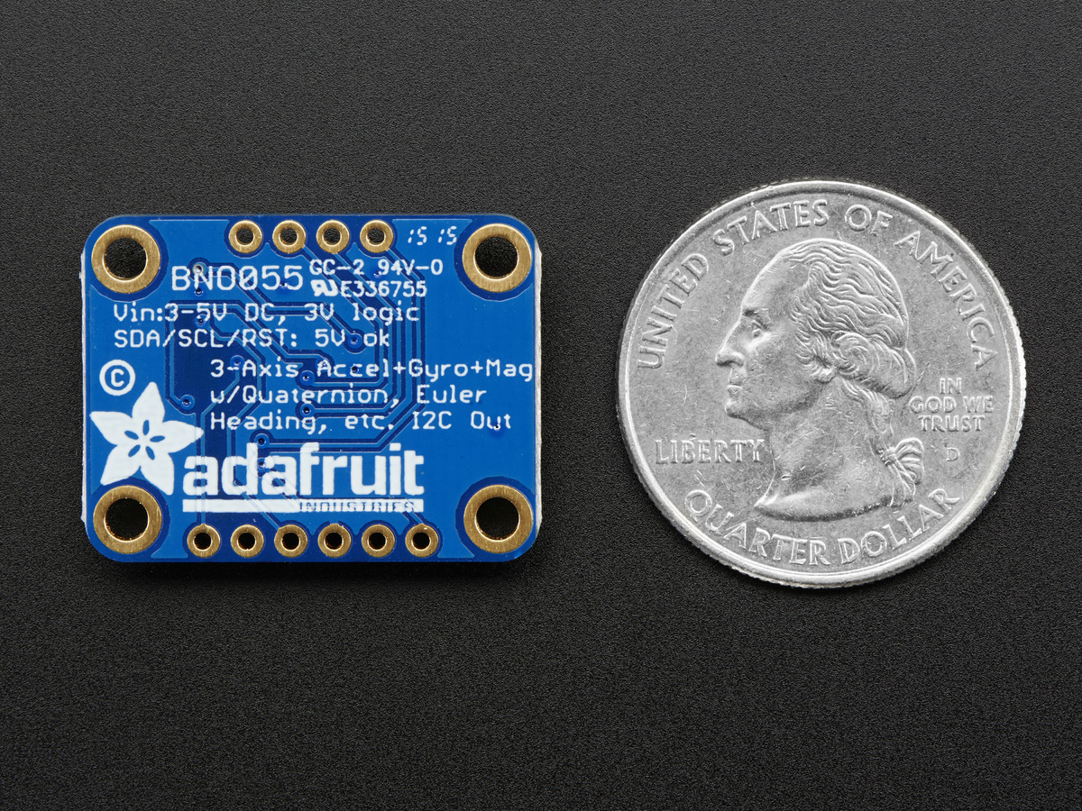
See https://www.adafruit.com/produ... for further product details.
So I have easy access to fused 3D orientation data but I don't know whether those data are correct -- i.e., whether my driver is really working. I could just display the values of the three axes on the target's on-board LCD screen but that is difficult to visualize in general.
Again, AdaFruit provides a much more satisfying approach. They have a demonstration for their IMU breakout board that uses data from the sensor to drive a 3D object modeled on the host computer. As the breakout board is rotated, the modeled object rotates as well, providing instant (and much more fun) indication of driver correctness.
The current version of the demonstration is described in detail here, using a web-based app to display the model. I got an earlier version that uses the "Processing" application to display a model, and instead of using their 3D model of a cat I use a model of the Apollo Lunar Excursion Module (LEM).
The LEM model is available from NASA, but must be converted to the "obj" model data format supported by the Processing app.
The Processing app is available here for free. Once downloaded and installed on the host, Processing can execute programs -- "sketches" -- that can do interesting things, including displaying 3D models. The AdaFruit demo provided a sketch for displaying their cat model. I changed the hard-coded file name to specify the LEM model and changed the relative size of the model, but that was about all that was changed.
The sketch gets the orientation data from a serial port, and since the sensor breakout board is connected to an STM32 Discovery board, we need that board to communicate over one of the on-board USART ports. The Ada Drivers Library includes all that is necessary for doing that, so the only issue is how to connect the board's USART port to a serial port on the host.
For that purpose I use a USB cable specifically designed to appear as a serial port on the host (e.g., a COM port on Windows). These cables are available from many vendors, including Mouser:
- Mouser Part No: 895-TTL-232R-5V
- Manufacturer Part No: TTL-232R-5V
- Manufacturer: FTDI
but note that the above is a 5-volt cable in case that is an issue. There are 3V versions available.
The end of the cable is a female header, described in the datasheet (DS_TTL-232R_CABLES-217672.pdf). Header pin 4 on the cable is TXD, the transmit data output. Header pin 5 on the cable is RXD, the receive data input. The on-board software I wrote that sends the sensor data over the port uses specific GPIO pins for the serial connection, thus I connected the cable header pins to the STMicro board's GPIO pins as follows:
- header pin 1, the black wire's header slot, to a ground pin on the board
- header pin 4, the orange wire's header slot, to PB7
- header pin 5, the yellow wire's header slot, to PB6
On the host, just plug in the USB-to-serial cable. Once the cable is connected it will appear like a host serial port and can be selected within the Processing app displaying the model. Apply power to the board and the app will start sending the orientation data.
The breakout board, STM32F429 Discovery board, and USB serial cable connections are shown in the following image. (Note that I connected a green wire to the USB cable's orange header wire because I didn't have an orange connector wire available.)

When we rotate the breakout board the LEM model will rotate accordingly, as shown in the following video:
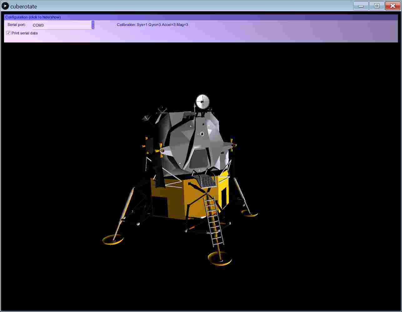
To display the LEM model, double-click on the "lander.pde" file to invoke the Processing app on that sketch file. Then press the Run button in the Processing app window. That will bring up another window showing the LEM model.
In the second window showing the lander, there is a pull-down at the upper left for the serial port selection. Select the port corresponding to the USB cable attached to the STM32 board's serial port. That selection will be recorded in a file named "serialconfig.txt" located in the same directory as the model so that you don't have to select it again, unless it changes for some reason.
Note that in that second window there is a check-box labeled "Print serial data." If you enable that option you will see the IMU data coming from the breakout board via the serial port, displayed in the main Processing app window. That data includes the current IMU calibration states so that you can calibrate the IMU (by moving the IMU board slowly along three axes). When all the calibration values are "3" the IMU is fully calibrated, but you don't need to wait for that -- you can start rotating the IMU board as soon as the model window appears.
The Ada Drivers Library is available here.
The Ada source code, the 3D LEM model, and the Processing sketch file for this example are available here.
About Pat Rogers

Dr. Patrick Rogers has been a computing professional since 1975, primarily working on embedded real-time applications including high-fidelity flight simulators and Supervisory Control and Data Acquisition (SCADA) systems controlling hazardous materials. He was director of the Ada9X Laboratory for the U.S. Air Force’s Joint Advanced Strike Technology Program, Principal Investigator in distributed systems and fault tolerance research projects using Ada for the U.S. Air Force and Army, and Associate Director for Research at the NASA Software Engineering Research Center. As a member of the Senior Technical Staff at AdaCore, he specializes in supporting real-time/embedded application developers, develops bare-board products and demonstrations, and creates training courses and presentations. He serves as Convenor of ISO/IEC JTC 1/SC 22/WG 9, the group responsible for the Ada standard.