Making an RC Car with Ada and SPARK
by Pat Rogers –
As a demonstration for the use of Ada and SPARK in very small embedded targets, I created a remote-controlled (RC) car using Lego NXT Mindstorms motors and sensors but without using the Lego computer or Lego software. I used an ARM Cortex System-on-Chip board for the computer, and all the code -- the control program, the device drivers, everything -- is written in Ada. Over time, I’ve upgraded some of the code to be in SPARK. This blog post describes the hardware, the software, the SPARK upgrades, and the repositories that are used and created for this purpose.
Why use Lego NXT parts? The Lego NXT robotics kit was extremely popular. Many schools and individuals still have kits and third-party components. Even if the latest Lego kit is much more capable, the ubiquity and low cost of the NXT components make them an attractive basis for experiments and demonstrations.
In addition, there are many existing NXT projects upon which to base demonstrations using Ada. For example, my RC car is based on the third-party HiTechnic IR RC Car. The car turns extremely well because it has an Ackerman steering mechanism, so that the inside wheel turns sharper than the outside wheel, and a differential on the drive shaft so that the drive wheels can rotate at different speeds during a turn. The original car uses the HiTechnic IR (infra-red) receiver to communicate with a Lego remote control. This new car uses that same receiver and controller, but also supports another controller communicating over Bluetooth LE.
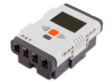
Replacing the NXT Brick
The NXT embedded computer controlling NXT robots is known as the “brick,” probably because of its appearance. (See Figure 1.) It consists of an older 48 MHz ARMv7, with 256 KB of FLASH and 64 KB of RAM, as well as an AVR co-processor. The brick enclosure provides an LCD screen, a speaker, Bluetooth, and four user-buttons, combined with the electronics required to interface to the external world. A battery pack is on the back.
Our replacement computer is one of the “Discovery Kit” products from STMicroelectronics. The Discovery Kits have ARM Cortex processors and include many on-package devices for interfacing to the external world, including A/D and D/A converters, timers, UARTs, DMA controllers, I2C and SPI communication, and others. Sophisticated external components are also included, depending upon the specific kit.
Specifically, we use the STM32F4 Discovery Kit which has a Cortex M4 MCU running at up to 168 MHz, a floating-point co-processor, a megabyte of FLASH and 192 KB of RAM. It also includes an accelerometer, MEMS microphone, audio codec, a user button, and four user LEDs. (See figure 2.) It is very inexpensive– approximately $15. Details are available here:
https://www.st.com/en/evaluation-tools/stm32f4discovery.html
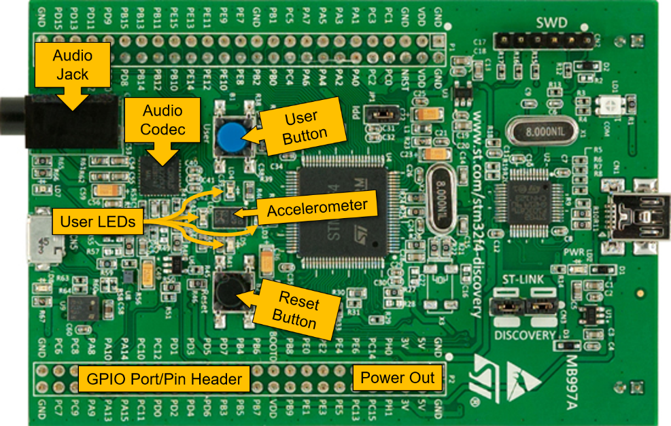
I made one change to the Discovery Kit board as received from the factory. Because the on-package devices, such as the serial ports, I2C devices, timers, etc. all share potentially overlapping groups of GPIO pins, and because not all pins are available on the headers, not all the pins required were exclusively available for all the devices needed for the RC car. Ultimately, I found a set of pin allocations that would almost work, but I needed pin PA0 to do it. However, pin PA0 is dedicated to the blue User button by a solder bridge on the underside of the board. I removed that solder bridge to make PA0 available. Of course, doing so disabled the blue User button but I didn’t need it for this project.
Replacing the NXT brick also removed the internal interface electronics for the motors and sensors. I used a combination of a third-party board and hand-made circuits to replace them. A brief examination of the motors will serve to explain why the additional board was chosen.
The Lego Mindstorms motors are 9-volt DC motors with a precise rotation sensor and significant gear reduction producing high torque. The motors rotate at a rate relative to the power applied and can rotate in either direction. The polarity of the power lines controls the rotation direction: positive rotates one way, negative rotates the other way.
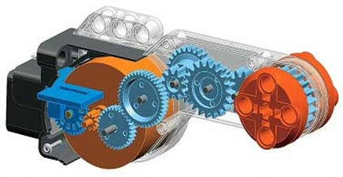
Figure 3 illustrates the partial internals of the NXT motor, including the gear train in light blue, and the rotation sensor to the left in dark blue, next to the motor itself in dark orange. (The dark gray part at far left is the connector housing.)
I mentioned that the polarity of the applied power determines the rotation direction. That polarity control requires an external circuit, specifically an ‘H-bridge” circuit that allows us to achieve that effect.
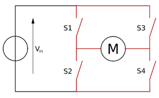
Figure 4 shows the functional layout of the H-bridge circuit, in particular the arrangement of the four switches S1 through S4 around the motor M. By selectively closing two switches and leaving the other two open we can control the direction of the current flow, and thereby control the direction of the motor rotation.
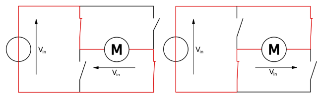
Figure 5 illustrates two of the three useful switch configurations. The red line shows the current flow. Another option is to close two switches on the same side and end, in which case the rotor will “lock” in place. Opening all the switches removes all power and thus does not cause rotation. The fourth possible combination, in which all switches are closed, is not used.
Rather than build my own H-bridge circuit I used a low-cost product dedicated to interfacing with NXT motors and sensors. In addition to the H-bridge circuits, they also provide filters for the rotation sensor’s discrete inputs so that noise does not result in too many false rotation counts. There are a number of these products available.
One such is the “Arduino NXT Shield Version 2” by TKJ Electronics: http://www.tkjelectronics.dk/ in Denmark. The product is described in their blog, here: http://blog.tkjelectronics.dk/2011/10/nxt-shield-ver2/ and is available for sale here: http://shop.tkjelectronics.dk/product_info.php?products_id=29 for a reasonable price.
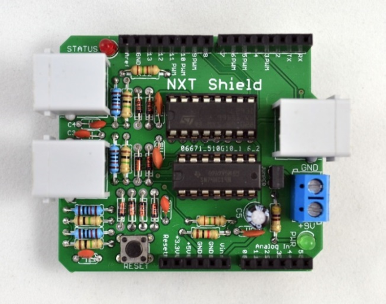
The “NXT Shield” can control two NXT motors and one sensor requiring 9 volts input, including a Mindstorms NXT Ultrasonic Sensor. Figure 6 shows the NXT Shield with the two standard NXT connectors on the left for the two motors, and the sensor connector on the right.
The kit requires assembly but it is just through-board soldering. As long as you get the diodes oriented correctly everything is straightforward. Figure 7 (below) shows our build, already located in an enclosure and connected to the Discovery Kit, power, two NXT motors, and the ultrasonic sensor.
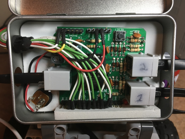
The in-coming 9 volts is routed to a DC power jack on the back of the enclosure, visible on the bottom left with red and black wires connecting it to the board. The 5 volts for the on-board electronics comes via the Discovery Kit header and is bundled with the white and green wires coming in through the left side in the figure. The enclosure itself is one of the “Make with Ada” boxes. “Make with Ada” is a competition offering serious prize money for cool projects using embedded targets and Ada. See http://www.makewithada.org/ for more information.
The power supply replacing the battery pack on the back of the NXT brick is an external battery intended for charging cell phones and tablets.
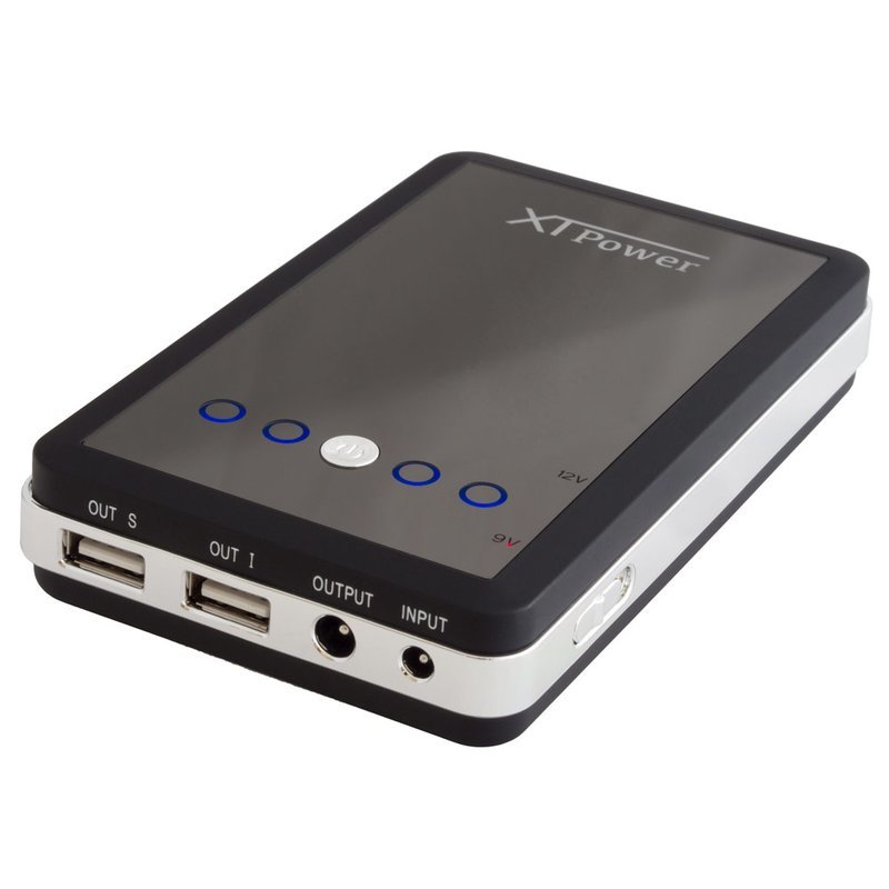
This battery provides separate connections for +5 and +9 (or +12) volts, which is very convenient: the +5V is provided via USB connector, which is precisely what the STM32F4 card requires, and both the NXT motors and the NXT ultrasonic sensor require +9 volts. The battery isn't light but holds a charge for a very long time, especially with this relatively light load. Note that the battery can also provide +12 volts instead of +9, selected by a physical slider switch on the side of the battery. Using +12 volts will drive the motors considerably faster and is (evidently) tolerated by the NXT Shield sensor circuit and the NXT Ultrasonic Sensor itself.
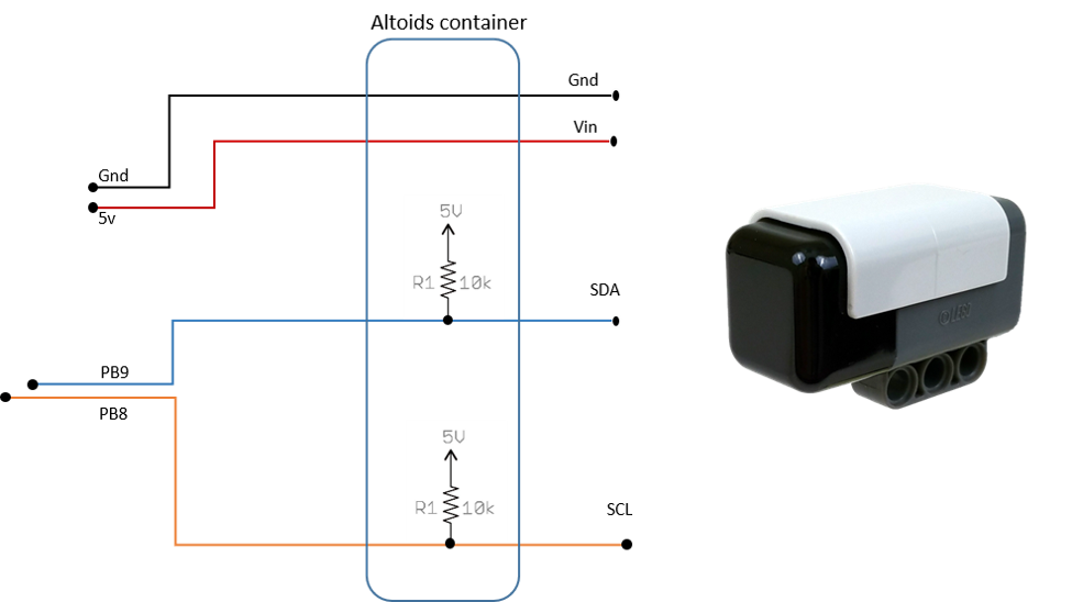
Finally, I required a small circuit supporting the I2C communication with the HiTechnic IR Receiver. The circuit is as simple as one can imagine: power, ground, and a pull-up resistor for each of the two I2C communication lines. These components are housed in the traditional Altoids tin and take power and ground from the Discovery Kit header pins. The communication lines go to specific GPIO header pins.
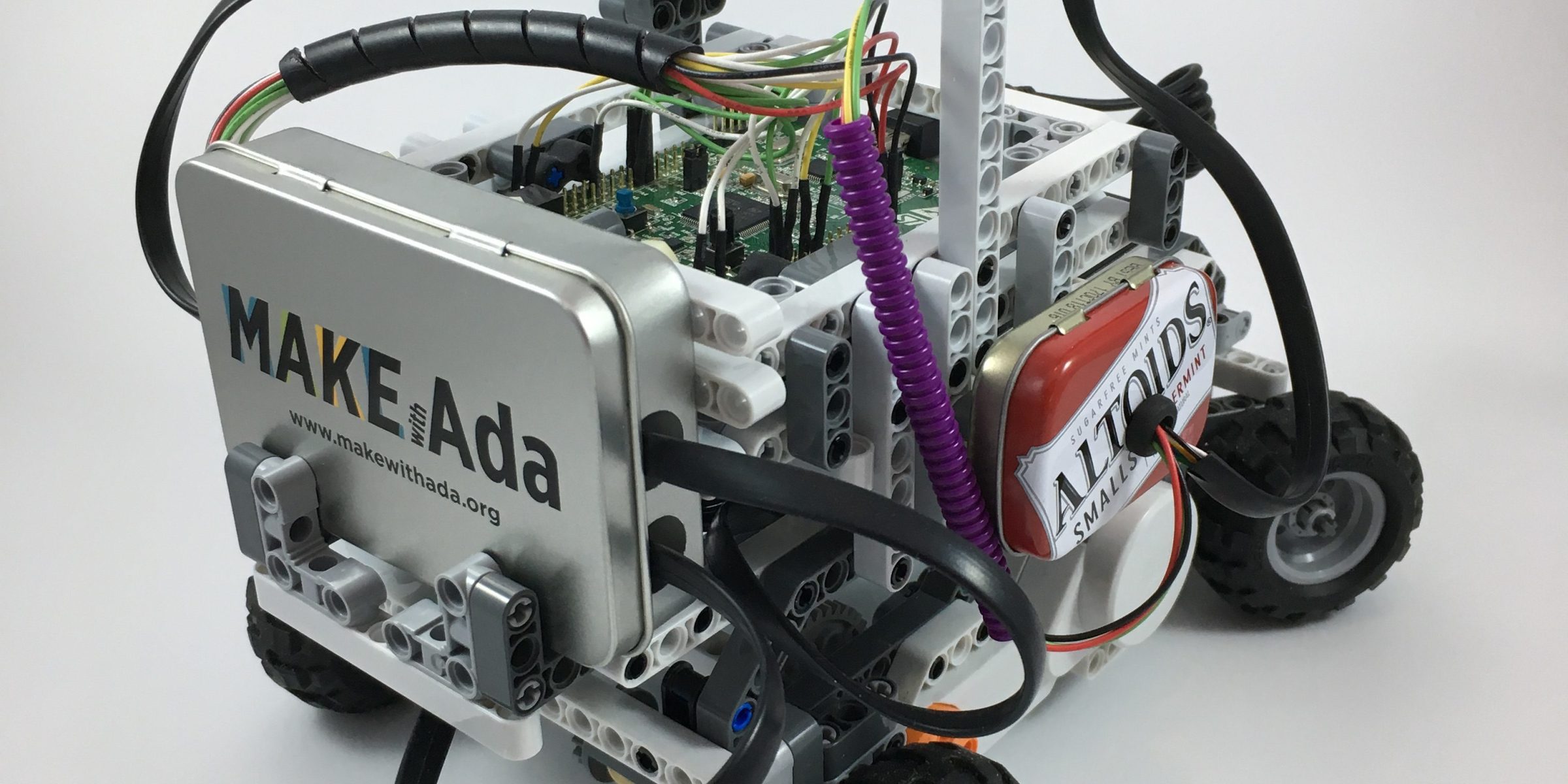
All of these replacements and the overall completed car (known as "Bob"), are shown in the following images:
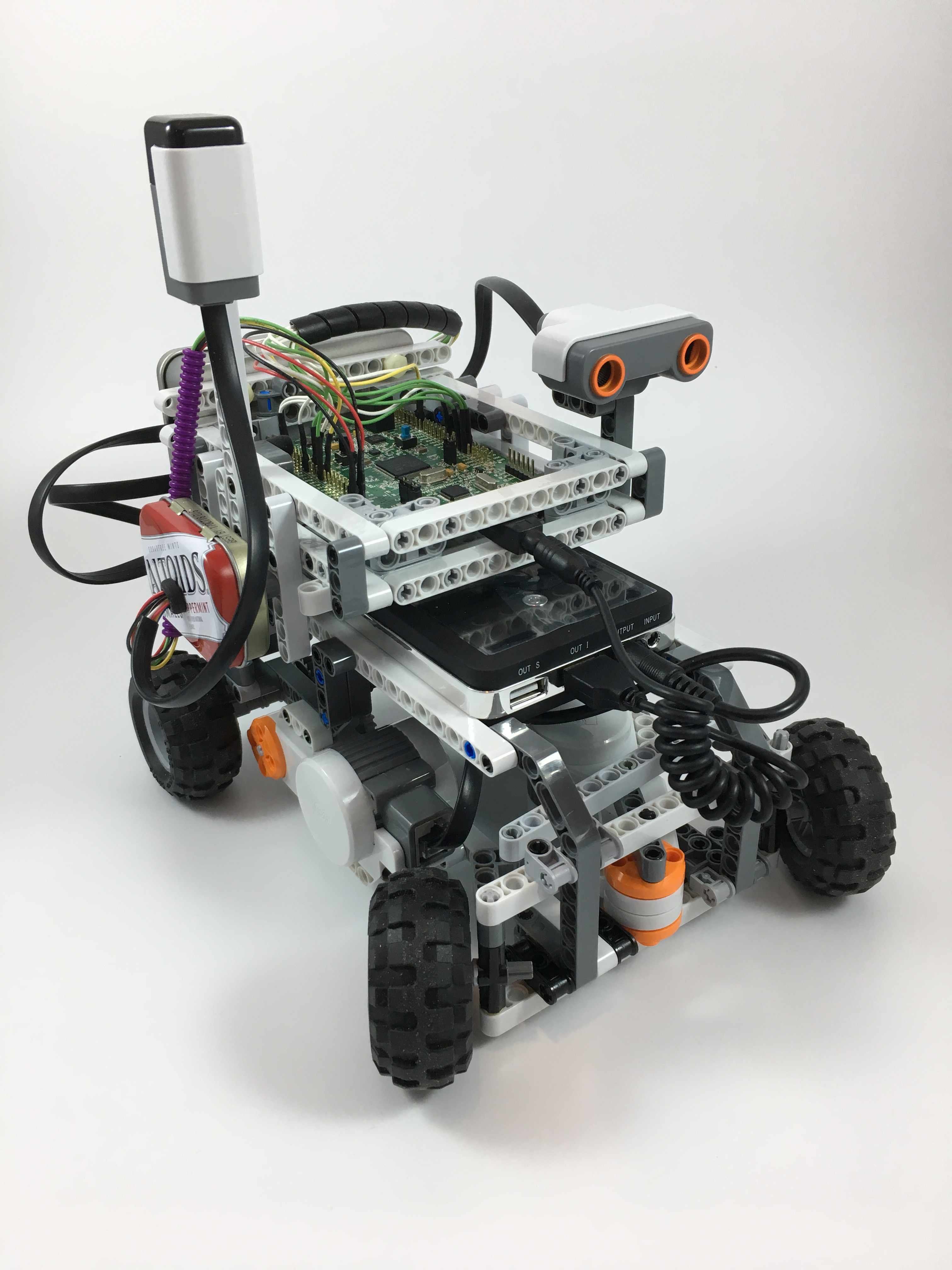
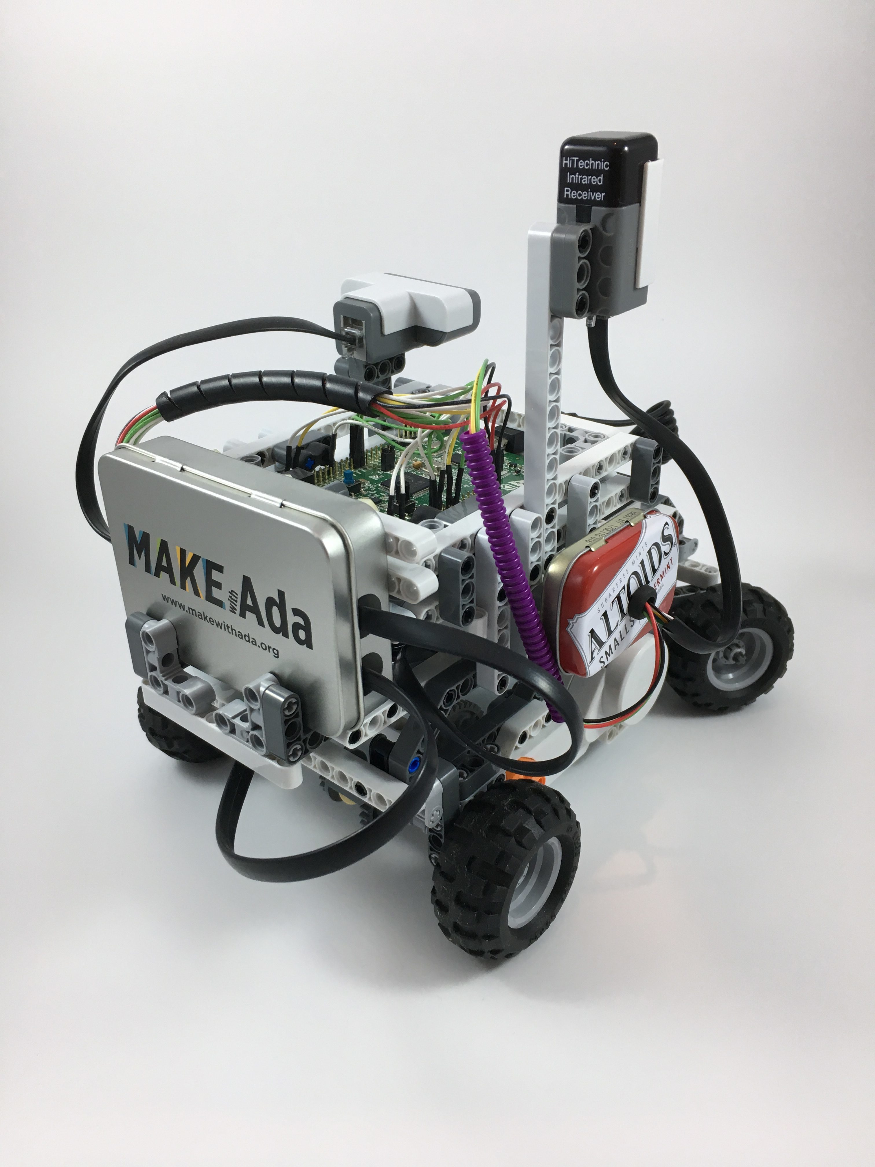
Figure 10 shows the rear enclosure containing the NXT Shield board, labeled “Make With Ada” on the outside, and the Altoids tin on the side containing the small circuit for the IR receiver.
Here is the car in action:
Replacing the NXT Software
The Ada Drivers Library (ADL) provided by AdaCore and the Ada community supplies the device drivers for the timers, I2C, A/D and D/A converters, and other devices required to replace those in the the NXT brick. The ADL supports a variety of development platforms from various vendors, including the STM32 series boards. The ADL is available on GitHub for both non-proprietary and commercial use here: https://github.com/AdaCore/Ada_Drivers_Library.
Replacing the brick will also require drivers for the NXT sensors and motors, software that is not included in the ADL. However, we can base them on the ADL drivers for our target board. For example, the motor rotary encoder driver uses the STM32 timer driver internally because those timers directly support quadrature rotation encoders. All these abstractions, including some that are not hardware specific, are in the Robotics with Ada repository: https://github.com/AdaCore/Robotics_with_Ada. This repo supports the NXT motors and all the basic sensors, as well as some third-party sensors. Abstract base types are used for the more complex sensors so that new sensors can be created easily using inheritance.
In addition, the repository contains some signal processing and control system software, e.g., a “recursive moving average” (RMA) noise filer type and a closed loop PID controller type. These require further packages, such as a bounded ring buffer abstraction.
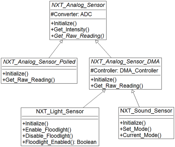
For example, the analog sensors (e.g., the light and sound sensors), have an abstract base class controlling an ADC, and two abstract subclasses using DMA and polling to transfer the converted data. The concrete light and sound sensor types are derived from the DMA-based parent type (figure 11).
The so-called NXT “digital” devices contain an embedded chip. These follow a similar design with an abstract base class and concrete subclass drivers for the more sophisticated, complex sensors. Lego refers to these sensors as “digital” sensors because they do not provide an analog signal to be sampled. Instead, the drivers both command and query the internal chips to operate the sensors.
The sensors’ chips use the NXT hardware cable connectors’ two discrete I/O lines to communicate. Therefore, a serial communications protocol based on two wires is applied. This communication protocol is usually, but not always, the “I2C” serial protocol. The Lego Ultrasonic Sonar sensor and the HiTechnic IR Receiver sensor both use I2C for communication. In contrast, version 2 of the Lego Color sensor uses the two discrete lines with an ad-hoc protocol.
The HiTechnic IR Receiver driver uses the I2C driver from the ADL for the on-package I2C hardware. That is a simple approach that also offloads the work from the MCU. The NXT Ultrasonic sensor, on the other hand, was a problem. I could send data to the Ultrasonic sensor successfully using the on-package I2C hardware (via the ADL driver) but could not get any data back. As discussed on the Internet, the problem is that the sensor does not follow the standard I2C protocol. It requires an extra communication line state change in the middle of the receiving steps. I could not find a way to make the on-package I2C hardware in the ARM package do this extra line change. The NXT Shield hardware even includes a GPIO “back door” connection to the I2C data line for this purpose, but I could not make that work with the STM32 hardware. Ultimately, I had to use a bit-banged approach in place of the I2C hardware and ADL driver. Fortunately, the vendor of the NXT Shield also provides the source code for an ultrasonic sensor driver in C++ using the Arduino “Wire” interface for I2C so I could see exactly what was required.
Bit-banging has system-wide implications. Since the software is doing the low-level communication instead of the on-package I2C hardware, interrupting the software execution in the middle of the protocol could be a problem. That would mean that the priority of the task handing the device must be sufficiently high relative to the other tasks in the system. Bit-banging also means an additional utilization of the MPU that would otherwise be offloaded to a separate I2C hardware device. Our application is rather simple, so processor overload is not a problem. Care with the task priorities was required, though.
You cannot hear the ultrasonic sensor pings, as the sensor name indicates. However, I recorded the videos on my cellphone and its microphone detects the pings. They are very directional, necessarily, so they are only heard in the video when the car is pointing at the phone. Here is another short video of the car, stationary, with the camera immediately in front. The pings are quite noticeable:
System Architecture
The overall architecture of the control software is shown below in figure 12.
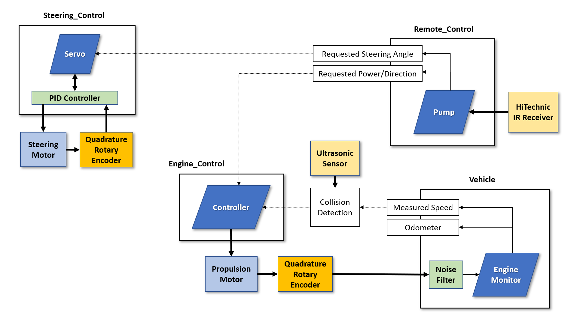
In the diagram, the parallelograms are periodic tasks (threads), running until power is removed. Each task is located inside a dedicated package. The Remote_Control package and the Vehicle package also provide functions that are callable by clients. Calls are indicated by dotted lines, with the arrowhead indicating the flow of data. For example, the Servo task in the Steering_Control package calls the Remote_Control package’s function to get the currently requested steering angle.
The Steering Motor and Propulsion Motor boxes represent the two NXT motors. Each motor has a dedicated rotary encoder inside the motor housing but the diagram depicts them as distinct in order to more clearly show their usage. The PID controller and vehicle noise filter are completely in software.
The PID (Proportional Integral Derivative) controller is a closed-loop control mechanism that uses feedback from the system under control to maintain a requested value. These mechanisms are ubiquitous, for example in your house's thermostat maintaining your requested heating and cooling temperatures. In our case, the PID controller maintains the requested steering angle using the steering motor's encoder data as the feedback signal.
The noise filter is a “recursive moving average” filter commonly used in digital signal processing to smooth sensor inputs. (Although the third-party interface board removed most encoder noise, some noise remained.) The PID controller did not require an encoder noise filter because the mechanical steering mechanism has enough “play” in it that encoder noise has no observable effect. The vehicle measured speed calculation, however, needed the filter because the values are used only within the software, not in a physical effector.
The collision detection logic determines whether a collision is imminent, using the NXT ultrasonic sensor data and the vehicle's current speed as inputs. If a sufficiently close object is detected ahead and the vehicle is moving forward, the engine Controller task stops the car immediately. Otherwise, such objects, if any, are ignored.
Application Source Code Example: Steering Servo
As the system diagram shows, the application consists of four primary packages, each containing a dedicated task. (There are other packages as well, but they do not contain tasks.) The task in the Steering_Control package is named “Servo” because it is acting as a servomechanism: it has a feedback control loop. In contrast, the task “Controller” in the Engine_Control package is not acting as a servo because it uses “open loop” control without any feedback. It simply sets the motor power to the requested percentage, with the resulting speed depending on the available battery power and the load on the wheels. I could also use a PID controller to maintain a requested speed, varying the power as required, but did not bother to do so in this version of the application.
The source code for the “Servo” task in the Steering_Control package is shown below, along with the declarations for two subprograms called by the task.
function Current_Motor_Angle (This : Basic_Motor) return Real with Inline;

procedure Convert_To_Motor_Values
  (Signed_Power : Real;
   Motor_Power  : out NXT.Motors.Power_Level;
   Direction    : out NXT.Motors.Directions)
with
  Inline,
  Pre => Within_Limits (Signed_Power, Power_Level_Limits);

task body Servo is
   Next_Release       : Time;
   Target_Angle       : Real;
   Current_Angle      : Real := 0.0;  -- zero for call to Steering_Computer.Enable
   Steering_Power     : Real := 0.0;  -- zero for call to Steering_Computer.Enable
   Motor_Power        : NXT.Motors.Power_Level;
   Rotation_Direction : NXT.Motors.Directions;
   Steering_Offset    : Real;
   Steering_Computer  : Closed_Loop.PID_Controller;
begin
   Steering_Computer.Configure
     (Proportional_Gain => Kp,
      Integral_Gain     => Ki,
      Derivative_Gain   => Kd,
      Period            => System_Configuration.Steering_Control_Period,
      Output_Limits     => Power_Level_Limits,
      Direction         => Closed_Loop.Direct);

   Initialize_Steering_Mechanism (Steering_Offset);

   Global_Initialization.Critical_Instant.Wait (Epoch => Next_Release);

   Steering_Computer.Enable (Current_Angle, Steering_Power);
   loop
      pragma Loop_Invariant (Steering_Computer.Current_Output_Limits = Power_Level_Limits);
      pragma Loop_Invariant (Within_Limits (Steering_Power, Power_Level_Limits));

      Current_Angle := Current_Motor_Angle (Steering_Motor) - Steering_Offset;

      Target_Angle := Real (Remote_Control.Requested_Steering_Angle);
      Limit (Target_Angle, -Steering_Offset, Steering_Offset);

      Steering_Computer.Compute_Output
        (Process_Variable => Current_Angle,
         Setpoint         => Target_Angle,
         Control_Variable => Steering_Power);

      Convert_To_Motor_Values (Steering_Power, Motor_Power, Rotation_Direction);

      Steering_Motor.Engage (Rotation_Direction, Motor_Power);

      Next_Release := Next_Release + Period;
      delay until Next_Release;
   end loop;
end Servo;
The PID controller object declared on line 19 is of a type declared in package Closed_Loop, an instantiation of a generic package. The package is a generic so that the specific floating-point input/output type is not hard-coded. The task first configures the PID controller object named Steering_Computer to specify the PID gain parameters, the interval at which the output routine is called, and the upper and lower limits for the output value (lines 21 through 27). The task then initializes the mechanical steering mechanism in order to get the steering offset (line 29). This offset is required because the steering angle requests from the user (via the remote control) are based on a frame of reference oriented on the major axis of the vehicle. Because I use the steering motor rotation angle to steer the vehicle, the code must translate the requests from the user's frame of reference (ie, the vehicle's) into the frame of reference of the steering motor. The steering motor's frame of reference is defined by the steering mechanism's physical connection to the car’s frame and is not aligned with the car’s major axis. Therefore, to do the translation the code sets the motor encoder to zero at some known point relative to the vehicle's major axis (line 29) and then handles the difference (line 38) between that motor "zero" and the "zero" corresponding to the vehicle. The code thus orients the steering motor's frame of reference to that of the vehicle, and hence to the user.
Having completed these local initialization steps, the Servo task then waits for the “critical instant” in which all the tasks should begin their periodic execution (line 31). The critical instant is time T0 (usually), so the main procedure passes a common absolute time value to each task from the Epoch formal parameter to the Next_Release variable. Each task uses its local Next_Release variable to compute its next iteration release time (lines 52 and 53) using the same initial epoch time. Waiting for this critical instant release also allows each task to wait for any prior processing in the main procedure to occur.
The task then enables the PID controller and goes into the loop. In each iteration, the task determines the current steering angle from the steering motor’s rotary encoder and the computed offset (line 38), gets the requested angle from the remote control and ensures it is within the steering mechanism’s physical limits (lines 40 and 41), then feeds the current angle and target angle into the PID controller (lines 43 through 46). The resulting output value is the steering motor power value required to reach the target angle.
The signed steering power is then converted into an NXT motor power percentage and rotation direction (line 48). Those values are used to engage the steering motor on line 50.
Finally, the task computes the next time it should be released for execution and then suspends itself until that point in time arrives (lines 52 and 53). All the tasks in the system use this same periodic looping idiom, as is expected for time-driven tasks in a Ravenscar tasking profile. (We are actually using the Jorvik tasking profile, based on Ravenscar and defined in Ada 202x. See http://www.ada-auth.org/standa...)
The PID controller is based on the Arduino PID library, version 1.1.1. The primary difference between my design and the Arduino design is that this Ada version does not compute the next time to execute. Instead, because Ada has such good real-time support, barring a design error we can be sure that the periodic task will call the PID output calculation routine at a fixed rate. Therefore, the Configure routine specifies this period, which is then used internally in the output computation. In addition, the PID object does not retain pointers to the input, setpoint, and output objects, for the sake of SPARK compatibility. We pass them as parameters instead.
For a great explanation of the Arduino PID design and implementation, step-by-step, see this web page:
http://brettbeauregard.com/blog/2011/04/improving-the-beginners-pid-introduction/
The PID controller abstract data type is declared within a generic package so that the input and output types need not be hard-coded. This specific implementation uses floating-point for the inputs and output, which gives us considerable dynamic range. The ARM MCU includes a floating-point unit so there is no performance penalty. However, if desired, a version using fixed-point types could be defined with the same API, trading some of the problems with floating point computations for problems with fixed-point computations. Neither is perfect.
SPARK Upgrade
One of my long terms goals for the RC Car was to upgrade to SPARK as much as possible. That effort is currently underway and some of the packages and reusable components are now in SPARK. For example, the Steering_Control package, containing the Servo task and PID controller object, are now at the Silver level of SPARK, meaning that it is proven to have no run-time errors, including no overflows. That is the reason for the loop invariants in the Servo task (lines 35 and 36 above), and the precondition on procedure Convert_To_Motor_Values (line 9 above). In particular, the provers needed to be told that the output value limits for the PID controller remain unchanged in each iteration, and that the value of the PID controller output variable remains within those limits.
Other parts of the software are merely in the SPARK subset currently, but some are at the highest level. The recursive moving average (RMA) filter uses a bounded ring buffer type, for example, that is at Gold level, the level of functional proof of unit correctness.
I will continue to upgrade the code to the higher levels, at least the Silver level for proving absence of runtime errors. Ultimately, however, this process will require changes to the ADL drivers because they use access discriminants which are not compatible with SPARK. That is the remaining issue preventing clean proof for the Vehicle package and its Controller task, for instance.
Source Code Availability
The full project for the RC car, including some relevant documents, is here: https://github.com/AdaCore/RC_...
About Pat Rogers

Dr. Patrick Rogers has been a computing professional since 1975, primarily working on embedded real-time applications including high-fidelity flight simulators and Supervisory Control and Data Acquisition (SCADA) systems controlling hazardous materials. He was director of the Ada9X Laboratory for the U.S. Air Force’s Joint Advanced Strike Technology Program, Principal Investigator in distributed systems and fault tolerance research projects using Ada for the U.S. Air Force and Army, and Associate Director for Research at the NASA Software Engineering Research Center. As a member of the Senior Technical Staff at AdaCore, he specializes in supporting real-time/embedded application developers, develops bare-board products and demonstrations, and creates training courses and presentations. He serves as Convenor of ISO/IEC JTC 1/SC 22/WG 9, the group responsible for the Ada standard.