Make With Ada 2020: High Integrity Sumobot
by Juliana Silva –
Blaine Osepchuk's project won a finalist prize in the Make with Ada 2019/20 competition. This project was originally posted on Hackster.io here. For those interested in participating in the 2020/21 competition, registration is now open and project submissions will be accepted until Jan 31st 2021, register here.
This document contains all the instructions you’ll need to build your own High Integrity Sumobot. This fully functional mini-sumobot is an advanced-level project programmed in Ada/SPARK and Arduino (C++).
Story
I created the High Integrity Sumobot using Ada/SPARK and high integrity software engineering techniques. I wanted to make it easy for people interested in Ada/SPARK to see how all the pieces fit together in a small embedded project.
I did my best to write simple, clean, and maintainable code throughout. It’s extensively commented and it’s open source so you can use it almost any way you want.
This document contains all the instructions you’ll need to build your own High Integrity Sumobot.
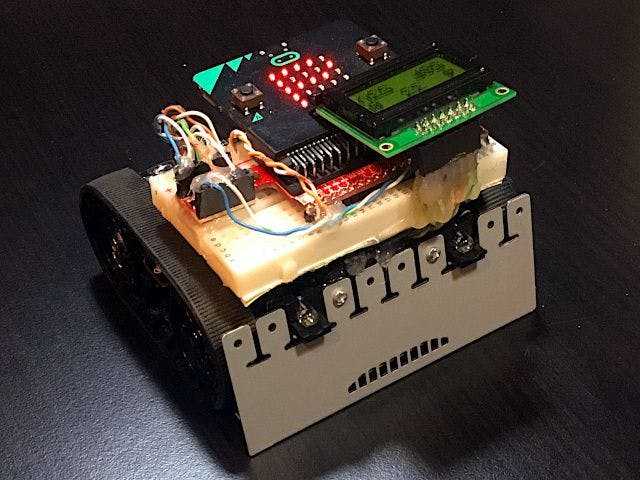
High Integrity Sumobot - Fighting Demo
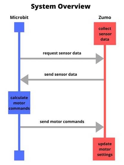
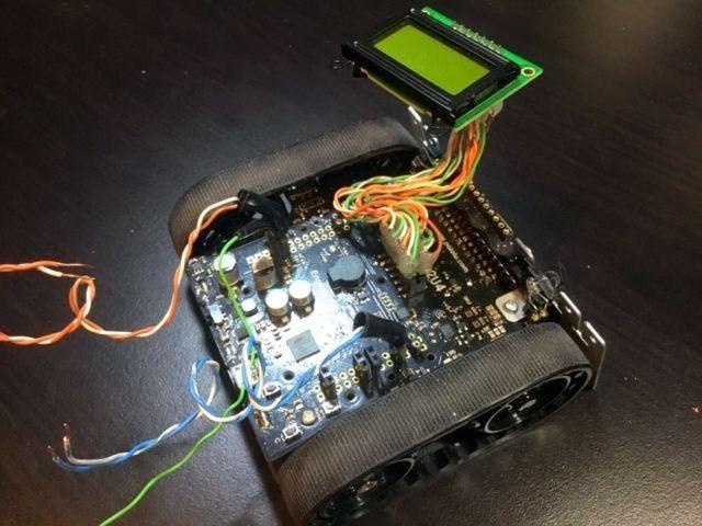
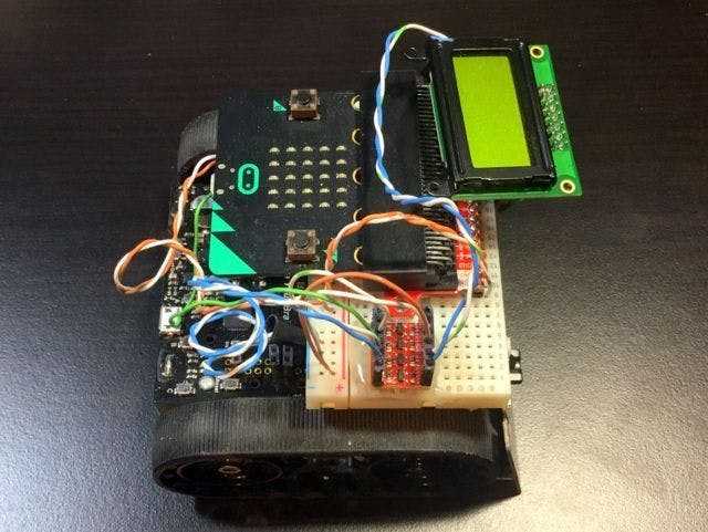
System overview
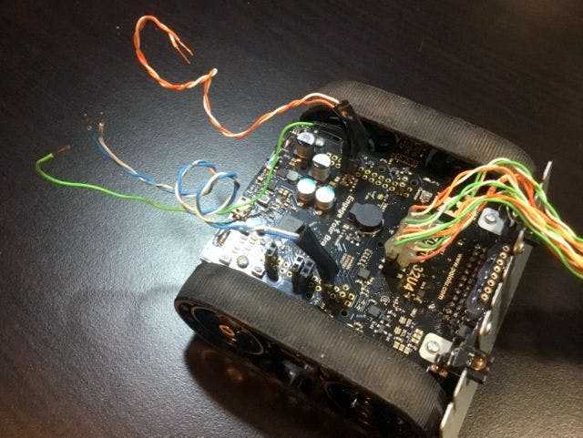
I started with a Zumo 32U4 sumobot. But instead of programming it directly as a microcontroller like most people do, I turned it into an I2C slave device, which I control with a microbit I programmed in Ada/SPARK.
The zumo continuously collects sensor data and stores it in a buffer. The microbit periodically requests sensor data from the zumo over I2C and the zumo sends the data it most recently collected. The microbit validates the sensor data, decides how the zumo should move, and sends motor commands back to the zumo (also over I2C). The zumo validates the motor commands and then executes them. And then the process repeats (at least 50 times per second).
The main job of a sumobot is to fight in sumo competitions. So the bulk of the code on the microbit is related to the fighting algorithm. Here’s a simplified state table for it:
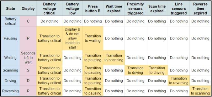
The 5 x 5 display on the microbit shows a character representing the current top-level state of the system (see the “Display” column of the state table above):
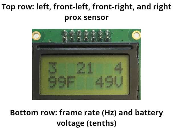
You can see the most important zumo parameters on the zumo’s LCD, which is helpful for development and debugging. It shows the following information:
My plan for achieving high integrity
I:
- followed a relaxed version of the personal software process (PSP). I did most the processes prescribed by PSP but because I am new to Ada/SPARK it didn’t make sense to do the tracking and analysis steps
- carefully implemented the smallest amount of functionality required to create the High Integrity Sumobot
- chose to do as much processing as possible on the microbit
- programmed the microbit in SPARK as much as possible, and fell back to Ada only where necessary
- programmed the microbit using simple constructs, constrained types, contracts, extensive data validation, formal proofs, and unit tests. I even proved functional correctness for some simple subprograms
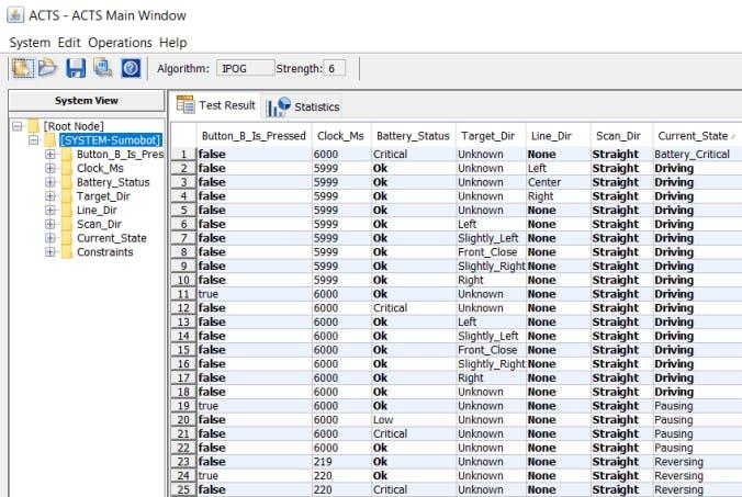
- programmatically generated test cases for the fighting algorithm to help ensure I tested all the important paths through the code
- made the zumo’s Arduino code is as simple as possible and much of it is covered by unit tests
- made extensive use of my personal code review checklist
- created written requirements and linked them to end-to-end tests to help ensure the High Integrity Sumobot works as intended
Parts
1 x microbit microcontroller1 x SparkFun micro:bit Breakout (with Headers)1 x Zumo 32u4 robot assembled with 75:1 motors. Note: the older, cheaper version of this robot (found here) will not work with this project1 x Breadboard – Self-Adhesive (White)1 x SparkFun Logic Level Converter – Bi-Directional (needed to convert the I2C signals back and forth from 3.3 to 5 volts because the microbit operates at 3.3 volts and the zumo operates at 5 volts)4 x AA NiMH batteries1 x Break Away Headers – Straight1 x Female Headers2 x Break Away Female Headers – Swiss Machine Pin (used for mounting the breadboard)2 x USB C cables1 x sumo ring (which you can buy or build yourself)misc parts: scavenged bits of wire, hot glue, solder, electrical tape, etc.
Getting up and running
I tested all of the steps below on Windows 7 and Windows 10 and the 2019 versions of GNAT Community and ARM ELF. Other platforms and versions may work but I have not tested them.
The ring and training dummy
- you’ll need some kind of ring to train your High Integrity Sumobot in. The specs for mini sumo rings can be found here. You can purchase a ring online but the shipping cost is probably going to be prohibitive. I didn’t have anything as big as the spec requires so I used a old piece of furniture and made the border with masking tape
- you’ll also need a training dummy, unless you have another robot to compete against. I made mine out of Lego but you could just as easily build one out of cardboard and hot glue

Arduino development environment and Zumo 32U4 setup
- install batteries in the zumo and turn it on. It comes pre-loaded with a sketch that demonstrates some of the features of the bot. Ensure your zumo works
- download and install the Arduino IDE. Note: I chose the windows installer, not the windows app (I’m not saying there’s anything wrong with the app, I just have no experience with it)
- start the Arduino IDE. You may be prompted to update your boards and libraries. Go ahead and do that
- install the windows drivers for the zumo
- configure the Arduino IDE to program the zumo 32U4. Make sure you can upload the blink demo to your zumo and confirm that it works
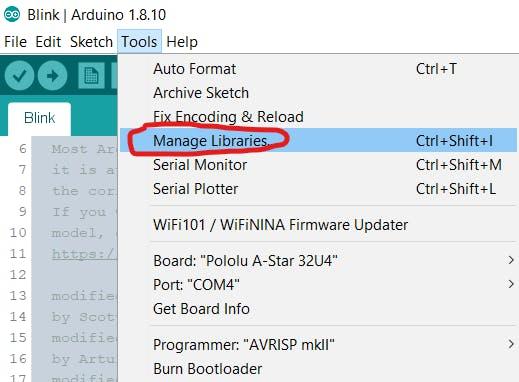
- in tools -> manage libraries install the following Arduino libraries: Zumo32U4 and ArduinoUnit
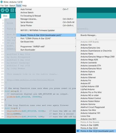
- normal uploading won’t work once the zumo and microbit are linked by I2C (because the I2C interrupts on the zumo interfere with uploading). So you’ll need use an alternative uploading method. You have to edit a file called boards.txt on your PC to enable the “Pololu A-Star 32U4 (bootloader port)” option in the tools -> boards menu. Follow the directions here under the “The bootloader-before-uploading method” to edit the boards.txt file. I found mine in “C:\Users\<username>\AppData\Local\Arduino15\packages\pololu-a-star\hardware\avr\4.0.2\boards.txt” on Windows 10 (your location might be different). Set your board to “Pololu A-Star 32U4 (bootloader port)”
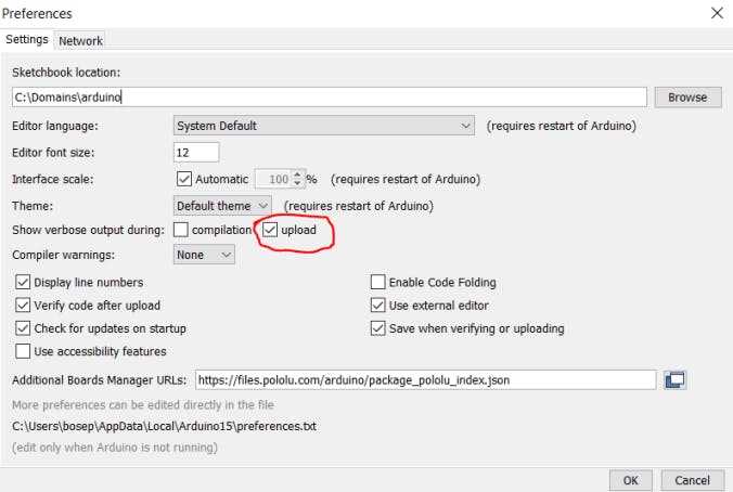
- turn on “verbose output during upload” so you can see why your upload failed (if it fails). Open file -> preferences and check the appropriate checkbox:
- try to upload the “face towards opponent” sketch onto the zumo using “The reset” and “The bootloader-before-uploading method” instructions described here. If that works, you are good to go

Ada/SPARK development environment setup
- setup your dev environment for Ada: https://blog.adacore.com/ada-on-the-microbit
- newer microbits are not recognized properly and will not flash. You can fix the problem with a one line change by following the directions here
- create a copy of the scrolling text demo project and flash it to your microbit as per the instructions here
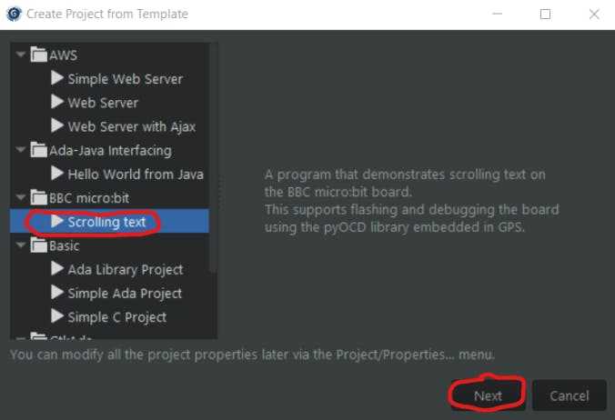
- “build all” and “flash to board” as shown in the screenshot below
- you should see “Make with Ada!” scroll across the 5 x 5 display on your microbit
- clone or download the Ada drivers library. Put the code wherever you want. You’ll need it for the next step
Create a copy of the project's code base
- clone the High Integrity Sumobot’s code base from GitHub
- edit the first line of the “microbit/high_integrity_sumobot.gpr” file to point to the location of your Ada drivers library code
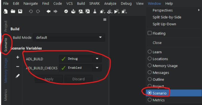
- open the project in GNAT Programming Studio (GPS)
- set scenario in GPS: “ADL_BUILD: debug”, “ADL_BUILD_CHECKS: enabled”. These settings turn on the compiler switches you need for development and production (turning contract checking off doesn’t increase the frame rate so you might as well leave it on so it can catch errors)
- build and flash the code to your microbit. The letter ‘U’ should show on the 5 x 5 display indicating an error (because the microbit is not in communication with the zumo yet)
Building your sumobot
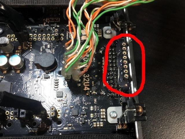
Zumo headers
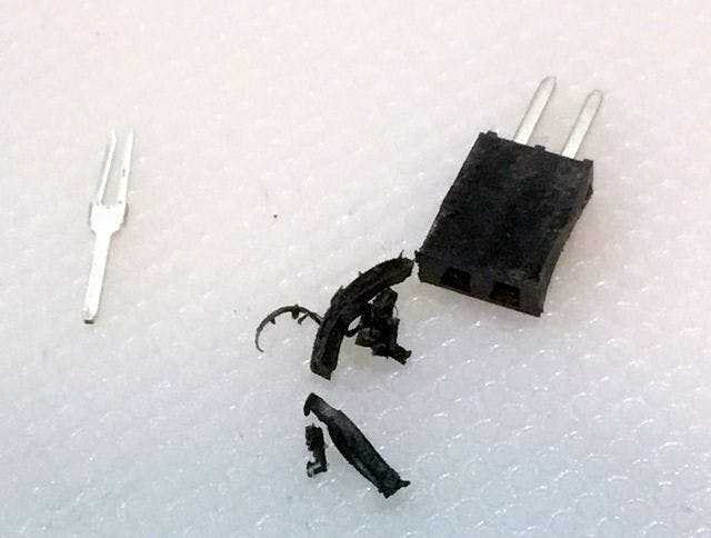
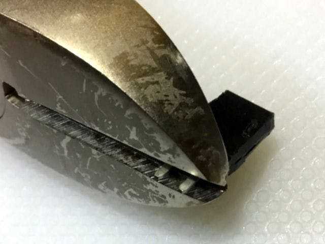
- cut 3 female headers into groups of two. Use a box cutter to make a deep groove into the next channel on both sides of the header, break the header on the cut marks, then trim the sharp edges and discard the pin you cut free
- trim the ends of the headers so it’s impossible for them to touch the batteries once they are soldered into place on the zumo (ruptured batteries are a safety risk)
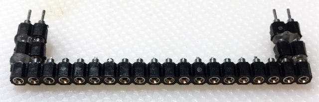
- cut 2 female swiss machine pin headers into groups of two
- solder the headers to the zumo. Three of the headers are for wiring (see the wiring diagram) and the other two are the rear mount points for the bread board
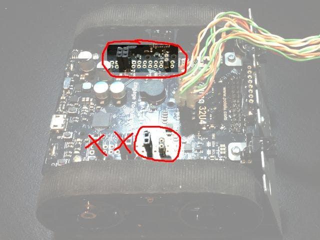
Note: you can ignore the headers that are crossed out in the image above (they are not used in this project).
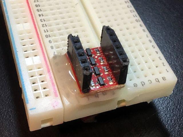
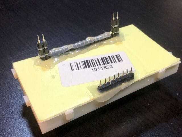
Level converter headers
- cut 2 female headers into groups of six and solder them to the side of the level converter containing the electronics
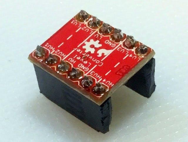
- set the level converter aside
LCD wiring harness
- make a wiring harness to free the LCD from the zumo main board. You’ll need two sets of male headers on one side and two sets of female headers on the other side. Make your wires 10 cm long. Solder all that together
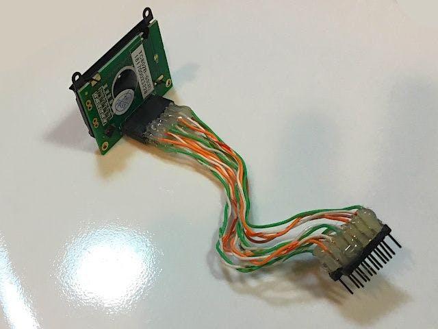
- install it in the zumo and turn it on to ensure the LCD still works
- remove the wiring harness from the zumo, hot glue all the solder joints so they can never short together, and then reinstall it between the zumo and the LCD

Zumo wires
- cut the five wires that connect to the zumo (5V, 3.3V, ground, I2C clock, and I2C data). Each wire should be 15 cm long
- strip both ends of each wire
- cut 3 male headers into groups of two
- solder the 3.3V and ground to a male header
- solder the I2C lines to the next male header
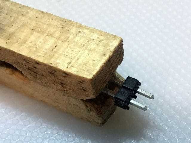
- and solder the 5V wire to the last male header (the other pin on that header isn’t soldered to anything). Note: a clothespin holds headers nicely while you solder them
- wrap the individual wires soldered to the male headers in electrical tape to prevent shorts
- insert the wires into the appropriate locations on the zumo
- position the ends of each wire away from the rear of the zumo so they are out of the way for the next steps
Breadboard
- remove the power rail from the breadboard closest to column A
- hot glue the level converter to the breadboard. Ensure the high voltage side is facing the rear of the bot (towards column J). Also ensure it is all the way to the edge or it will conflict with the microbit breakout board when you install it
- use female swiss machine pin headers and hot glue to make the rear mounting points for the breadboard. Trim the pins on the long header as shown below to make more room for your wires. You might have to experiment to get the breadboard to a sufficient height from the zumo to allow all your wiring to fit between the zumo and the breadboard, depending on the thickness and length of your wiring
- bend the LCD wiring harness so that the LCD sits just above the breadboard
- cut two female swiss machine pin headers into groups of 8 to make the front mount points for the breadboard
- test mount the breadboard on the zumo. If you’re happy with that glue one half of the front mount to the zumo
- install (but do not glue) the breadboard headers on the zumo so you can simply place the breadboard on top of your mount points
- if you’re happy with how your breadboard sits on the mount points remove the breadboard, put hot glue on top of the mounting headers, and then gently lower the breadboard onto the mount points. Note: do not glue all the mount points yet. You should be able to install and remove the breadboard easily with only gravity and friction holding it to the zumo.
- put a row of hot glue on the rear mount point where you cut the pins off in a previous step to prevent the pins from rubbing your wiring. The bottom of your breadboard should look like this:
Populating the breadboard
- hot glue a single female swiss machine pin header under the left and right sides of the breakout board to hold it level against the breadboard
- insert the microbit breakout board into the breadboard from B9 to B30
- insert the microbit into the breakout board with the display and buttons facing up
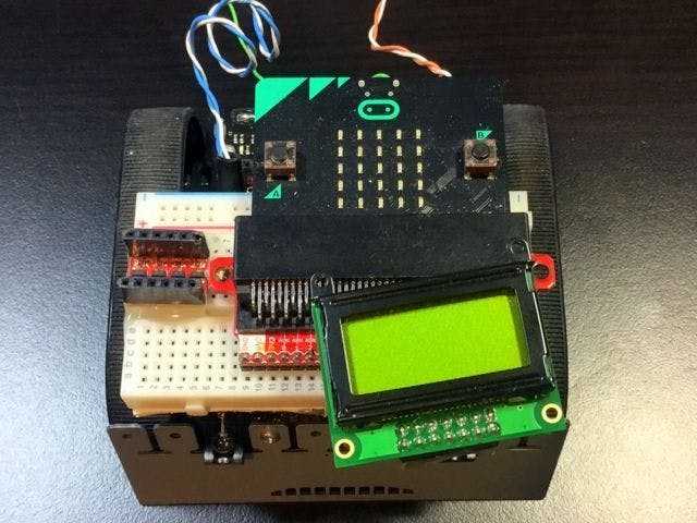
- mount the breadboard to the zumo mount points
- make the wires that connect from the breadboard to the level converter, leaving the wires longer than required and stripping the ends
- connect all the wires as per the wiring diagram
Uploading code and testing your sumobot
- configure the zumo portion of the project to run its unit tests (see instructions in the loop function of zumo.ino) upload the code to the zumo and open the serial monitor to see the results
- turn off the unit tests and upload the code to the zumo again
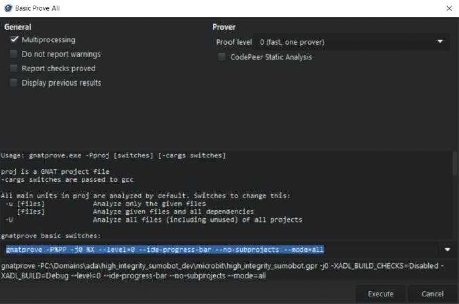
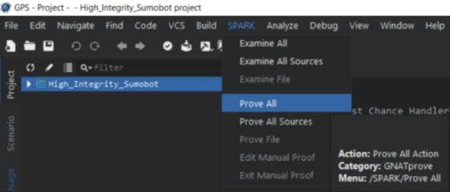
- run “prove all” on the microbit code in SPARK. Command template: “gnatprove -P%PP -j0 %X –level=0 –ide-progress-bar –no-subprojects –mode=all” (if gnatprove complains about ‘uncompiled dependencies’ add “-f” to the command and try again)
- configure the microbit portion of the project to run its unit tests (see instructions in main.adb) and flash them to the microbit. The number of passed assertions will scroll across the display if all the unit tests passed. A filename and line number will scroll across the display for the first failed test encountered
- turn off the microbit unit tests and flash the code to the microbit
- put your bot in your ring by itself and confirm it drives around searching for targets without leaving the ring
- also confirm that it can find and push your training dummy out of the ring
- you can also run the end-to-end tests if you like
Finishing up the build (optional)
If your High Integrity Sumobot is working but you want to make it a little more durable you can do these steps:
- hot glue the breadboard mounting points more permanently
- shorten the wires and hot glue them to the breadboard and level converter so they don’t come loose or snag during a fight
- hot glue the LCD wiring harness to the side of the breadboard
- give your bot another test alone in the ring and then with the training dummy to confirm it is operating correctly
Information for the Make with Ada judges
- I created this project as a solo effort (no teammates)
- all of the code in the GitHub for the High Integrity Sumobot was created by me for this contest. However, the algorithm for this bot was inspired by a demo in the zumo library, which you can find here. I modified the code extensively but it still retains some of the state machine, variable names, and comments from the original demo. And the body of the last chance handler is roughly based on some code I found online, the source of which is documented in that file
- none of the code in this project has been submitted in a previous Make with Ada competition
- I realize that you won’t be able to easily run the code for this project without actually building the High Integrity Sumobot. But you can run the microbit unit tests if you have a microbit. And you can also run the zumo unit tests by uploading the code to almost any Arduino compatible microcontroller. After that you have gnatprove, other kinds of static analysis, and code reading
- I plan to continue working on this project after the contest close date so please make sure you checkout the correct version of the code. I created release 0.1.0 just for you
- I wanted to make sure you didn’t miss the written requirements and end-to-end tests in this 3, 200 word document. I think they are important but have never seen them emphasized in a project write-up
Finally, I just wanted to make my case for why this project should score well for the “buzz effect” judging criteria. I spent a great deal of time brainstorming projects that might have “buzz effect” and reviewing all the other projects I could find that have used the Ada Drivers Library and this project is appealing on a number of fronts.
First, many universities, schools, and clubs already have mini-sumo competitions because fighting robots are a fun and easy way to learn embedded software development. And for an extra ~$30 over the cost of the sumobot they were already going to buy, people can build this project, improve upon the code, and actually use Ada/SPARK in a project they care about. Therefore, I believe a sumobot programmed in Ada/SPARK should be relatively easy to market and promote.
Secondly, this project’s code base (excluding tests) is actually pretty small and the objectives of the sumobot are easy to understand. So, diving into the code base and making changes shouldn’t be too intimidating as compared to the Certyflie project, for example. And yet, the opportunities for improvements are vast. I can imagine a class of students starting with this code base, then having everyone making different improvements, and then competing to see who does the best.
Thirdly, this project is my first with Ada/SPARK and I couldn’t find any accessible examples of how to use the high dependability features of these languages or much guidance for how I should use them in the context of a full project. The book Building High Integrity Applications with SPARK was the best resource I found but even it was lacking in several areas. I’m sure I misused some features of Ada/SPARK and you guys are going to get a chuckle out of it but this is the kind of example I looked for and couldn’t find when I started this competition.
Fourthly, I tried to use not just Ada/SPARK but an entire suite of processes (within the time I had available) that would help ensure a high quality, low defect project. I think that’s where the benefits of Ada/SPARK really kick in and it reinforces the case for possibly using this project as a learning example.
Future improvements
- get gnattest working and port the homemade unit tests to gnattest
- replace the breadboard and wires with a custom-made circuit board (less likely to malfunction or suffer damage in competition)
- 3D print a cover (to protect the hardware on top of the zumo)
- write proofs for more of the code
- use more of the zumo’s sensors and/or add additional sensors
- use the motor encoders to compensate for the effect battery voltage has on the sumobot’s speed (speed differences mess with the optimal time limits in the fighting algorithm)
- improve the fighting algorithm/add new algorithms (there is plenty of unused RAM and flash available on the microbit)
Resources
- zumo user’s guide
- zumo code library
- zumo code library documentation
- microbit hardware overview
- microbit hardware pins
Final thoughts
I loved working on this project. It was interesting switching back and forth between C++ on the zumo and Ada/SPARK on the microbit. I’ve got about 10 years of experience building projects on the Arduino platform so I was able to jump right in on that side. Whereas the learning curve in SPARK and Ada were pretty steep.
But, once I got into it, I started to resent the Arduino compiler for not catching all the stupid ways C++ allows you to write incorrect programs that the Ada compiler would have caught. I also came to appreciate how clearly the Ada compiler told me exactly what I did wrong when I did make a mistake. And, by the end of the project, I had a lot more confidence in the correctness of the Ada/SPARK code as compared to the Arduino code. I can totally see why the AdaCore people are so excited about Ada/SPARK.
If you decide to build your very own High Integrity Sumobot or have questions about it, I’d love to hear from you in the comments below. Finally, if you find any bugs in this project please report them here.
Thanks for reading all the way to the end. Cheers.