Writing on Air
by Jorge Real (Universitat Politècnica de València) –
While
searching for motivating projects for students of the Real-Time
Systems course here at Universitat Politècnica de València, we found a curious device that produces a
fascinating effect. It holds a 12 cm bar from its bottom and makes it
swing, like an upside-down pendulum, at a frequency of nearly 9 Hz.
The free end of the bar holds a row of eight LEDs. With careful and
timely switching of those LEDs, and due to visual persistence, it
creates the illusion of text... floating in the air!
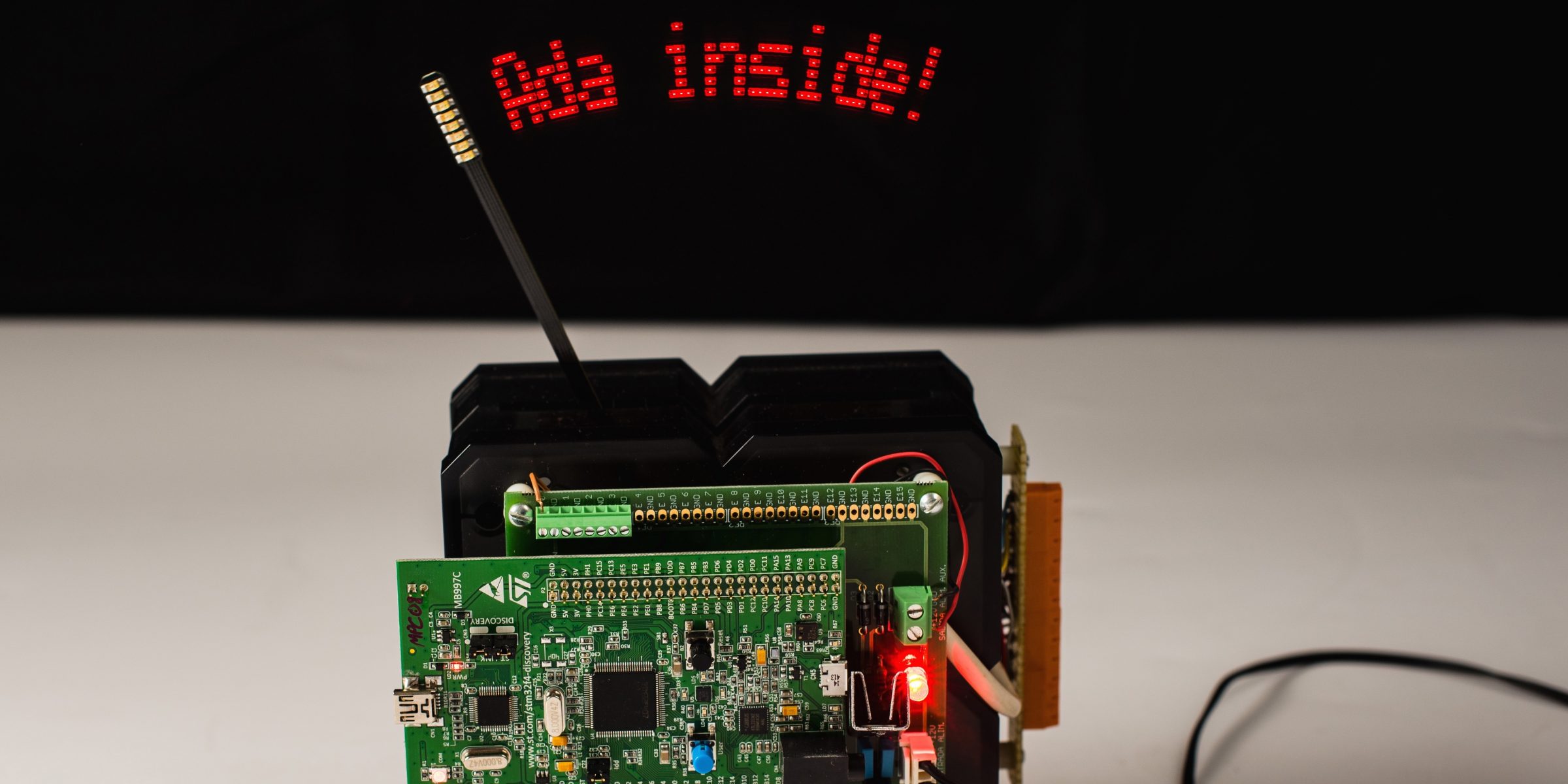
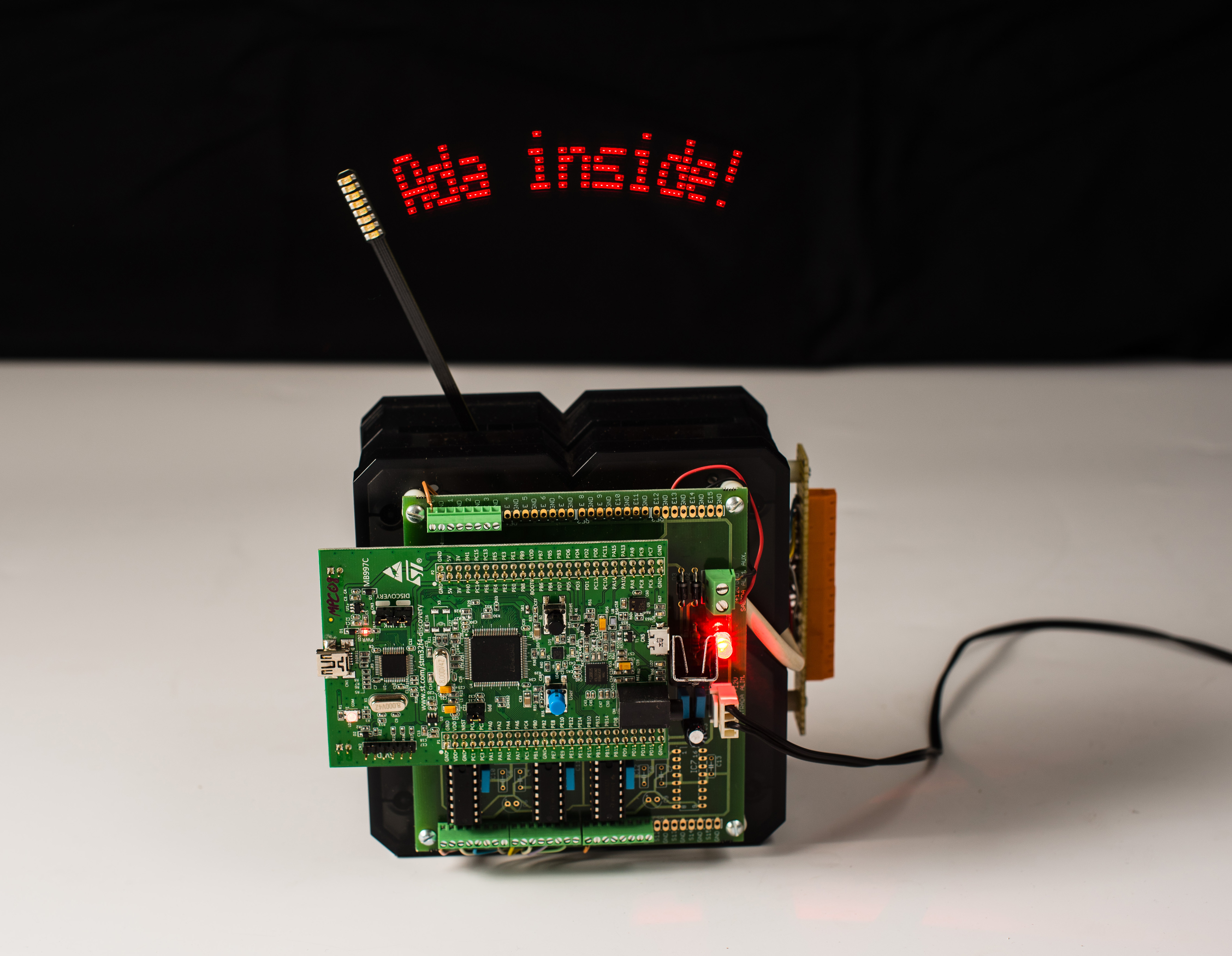
The web shows plenty of references to different realizations of this idea. They are typically used for displaying date, time, and also rudimentary graphics. Try searching for "pendulum clock LED", for example. The picture in Figure 1 shows the one we are using.
The software behind this toy is a motivating case for the students, and it contains enough real-time and synchronisation requirements to also make it challenging.
We have equipped the lab with a set of these pendulums, from which we have disabled all the control electronics and replaced them with STM32F4 Discovery boards. We use also a self-made interface board (behind the Discovery board in Figure 1) to connect the Discovery with the LEDs and other relevant signals of the pendulum. The task we propose our students is to make it work under the control of a Ravenscar program running on the Discovery. We use GNAT GPL 2016 for ARM hosted on Linux, along with the Ada Drivers Library.
There are two different problems to solve: one is to make the pendulum bar oscillate with a regular period; the other one is to then use the LEDs to display some text.
Swing that bar!
The bar is fixed from the bottom to a flexible metal plate (see Figure 2). The stable position of the pendulum is vertical and still. There is a permanent magnet attached to the pendulum, so that the solenoid behind it can be energised to cause a repulsion force that makes the bar start to swing.
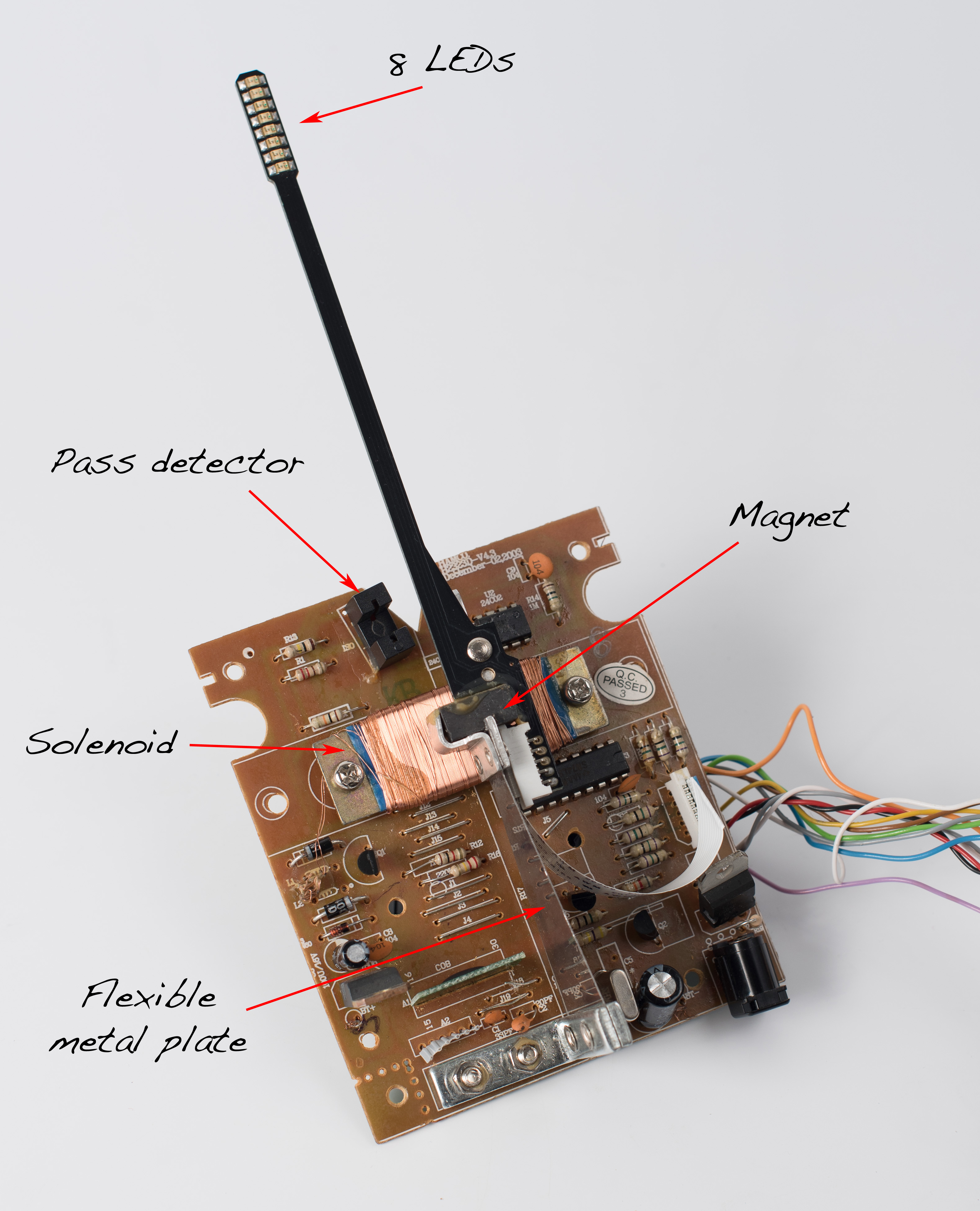
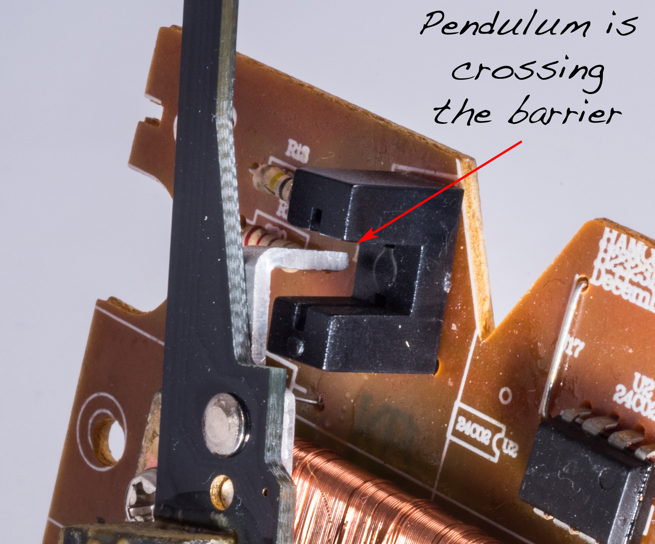
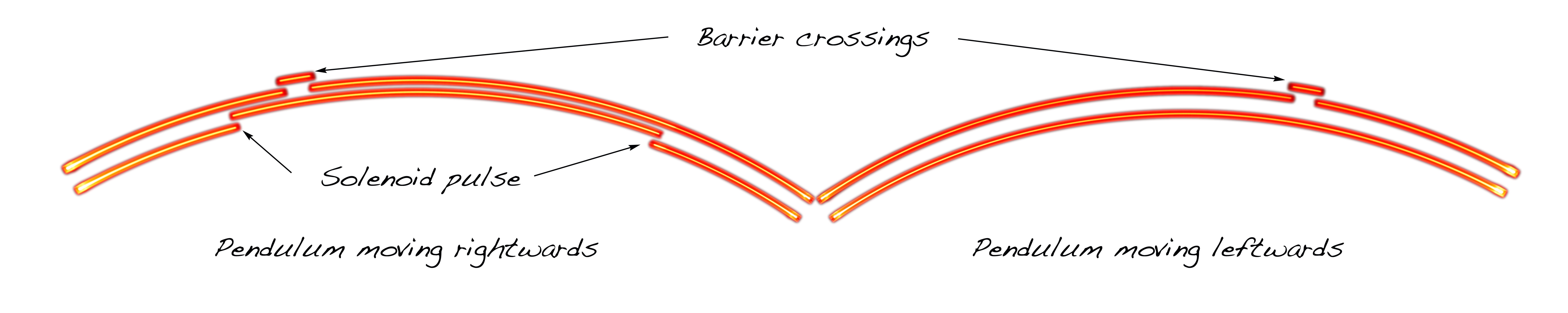
At startup, the solenoid control is completely blind to the whereabouts of the pendulum. An initial sequence must be programmed with the purpose of moving the bar enough to make it cross the barrier (see detail in Figure 3), a pass detector that uses an opto-coupler sensor located slightly off-center the pendulum run. This asymmetry is crucial, as we'll soon see.
Once the bar crosses the barrier at least three times, we have an idea about the pendulum position along time and we can then apply a more precise control sequence to keep the pendulum swinging regularly. The situation is pretty much like swinging a kid swing: you need to give it a small, regular push, at the right time. In our case, that time is when the pendulum enters the solenoid area on its way to the right side, since the solenoid repels the pendulum rightwards. That happens at about one sixth of the pendulum cycle, so we first need to know when the cycle starts and what duration it has. And for that, we need to pay close attention to the only input of the pendulum: the barrier signal.
Figure 4 sketches a chronogram of the barrier signal. Due to its asymmetric placement, the signal captured from the opto-coupler is also asymmetric.
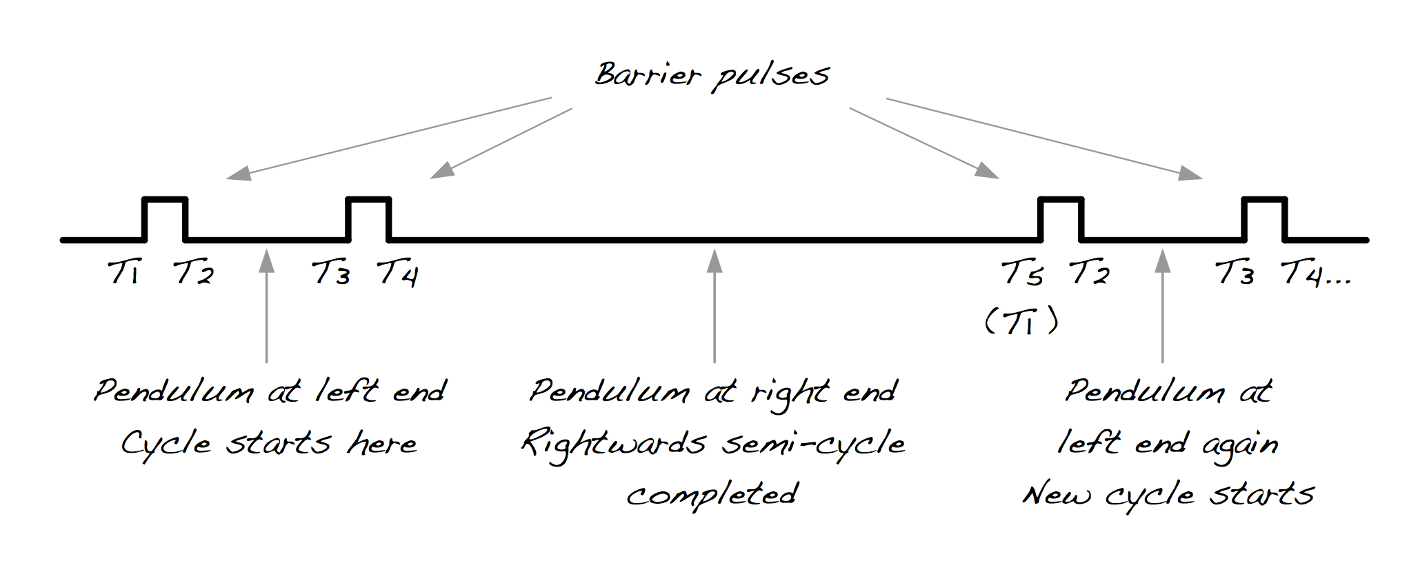
To determine the start time and period of the next cycle, we take note of the times when rising and falling edges of the barrier signal occur. This is easy work for a small Finite State Machine (FSM), triggered by barrier interrupts to the Discovery board. Once we have collected the five edge times T1 to T5 (normally would correspond to 2 full barrier crossings plus the start of a third one) we can calculate the period by subtracting T5 - T1. Regarding the start time of the next cycle, we know the pendulum initiated a new cycle (reached its left-most position) just in between the two closest pulses (times T1 and T4). So, based on the information gathered, we estimate that the next cycle will start at time T5 + (T4 - T1) / 2.
But… all we know when we detect a barrier edge is whether it is rising or falling. So, when we detect the first rising edge of Barrier, we can't be sure whether it corresponds to T1 (the second barrier crossing) or T3 (the first). We have arbitrarily guessed it is T1, so we must verify this guess and fix things if it was incorrect. This check is possible precisely due to the asymmetric placement of the pass detector: if our guess was correct, then T3 - T1 should be less than T5 - T3. Otherwise we need to re-assign our measurements (T3, T4 and T5 become T1, T2 and T3) and then move on to the adequate FSM state (waiting for T4).
Once we know when the pendulum will be in the left-most position (the cycle start time) and the estimated duration of the next cycle, we can give a solenoid pulse at the cycle start time plus one sixth of the period. The pulse duration, within reasonable range, affects mostly the amplitude of the pendulum run, but not so much its period. Experiments with pulse durations between 15 and 38 milliseconds showed visible changes in amplitude, but period variations of only about 100 microseconds, for a period of 115 milliseconds (less than 0.1%). We found 18-20 ms to work well.
So, are we done with the pendulum control? Well... almost, but no, we’re not: we are also concerned by robustness. The software must be prepared for unexpected situations, such as someone or something suddenly stopping the bar. If our program ultimately relies on barrier interrupts and they do not occur, then it is bound to hang. A timeout timing event is an ideal mechanism to revive a dying pendulum. If the timeout expires, then the barrier-based control is abandoned and the initialisation phase engaged again, and again if needed, until the pendulum makes sufficient barrier crossings to let the program retake normal operation. After adding this recovery mechanism, we can say we are done with the pendulum control: the bar will keep on swinging while powered.
Adding lyrics to that swing
Once the pendulum is moving at a stable rate, we are ready to tackle the second part of the project: using the eight LEDs to display some text. Knowing the cycle start time and estimated period duration, one can devise a plan to display each line of a character at the proper period times. We have already calculated the next cycle start time and duration for the pendulum control. All we need to do now is to timely provide that information to a displaying task.

The pendulum control functions described above are implemented by a package with the following (abbreviated) specification:
with STM32F4;       use STM32F4;
        with Ada.Real_Time; use Ada.Real_Time;

        package Pendulum_IO is

           --  Set LEDs using byte pattern (1 => On, 0 => Off)
           procedure Set_LEDs (Pattern : in Byte);

           --  Synchronization point with start of new cycle
           procedure Wait_For_Next_Cycle (Init_Time      : out Time;
                                          Cycle_Duration : out Time_Span);

        private
              task P_Controller with Storage_Size => 4 * 1024;
        end Pendulum_IO;
The specification includes subprograms for setting the LEDs (only one variant shown here) and procedure Wait_For_Next_Cycle, which in turn calls a protected entry whose barrier (in the Ada sense, this time) is opened by the barrier signal interrupt handler, when the next cycle timing is known. This happens at time T5 (see Figure 4), when the current cycle is about to end but with sufficient time before the calling task must start switching LEDs. The P_Controller task in the private part is the one in charge of keeping the pendulum oscillating.
Upon completion of a call to Wait_For_Next_Cycle, the caller knows the start time and period of the next pendulum cycle (parameters Init_Time and Cycle_Period). By division of the period, we can also determine at what precise times we need to switch the LEDs. Each character is encoded using an 8 tall x 5 wide dot matrix, and we want to fit 14 characters in the display. Adding some left and right margins to avoid the slowest segments, and a blank space to the right of each character, we subdivide the period in 208 lines. These lines represent time windows to display each particular character chunk. Since the pendulum period is around 115 milliseconds, it takes just some 550 microseconds for the pendulum to traverse one line.
If that seems tight, there is an even tighter requirement than this inter-line delay. The LEDs must be switched on only during an interval between 100 and 200 microseconds. Otherwise we would see segments, rather than dots, due to the pendulum speed. This must also be taken into account when designing the plan for the period, because the strategy changes slightly depending on the current pendulum direction. When it moves from left to right, the first 100 microseconds of a line correspond to it's left part, whereas the opposite is true for the opposite direction.
Dancing with the runtime
Apart
from careful planning of the sequence to switch the LEDs, this part
is possibly less complex, due to the help of Wait_For_Next_Cycle.
However, the short delays imposed by the pendulum have put us in
front of a limitation of the runtime support. The first try to
display some text was far from satisfactory. Often times, dots became
segments. Visual glitches happened all the time as well. Following
the track to this issue, we ended up digging into the Ravenscar
runtime (the full version included in GNAT GPL 2016) to eventually
find that the programmed precision for timing events and delay
statements was set to one millisecond. This setting may be fine for less
demanding applications, and it causes a relatively low runtime overhead;
but it was making it impossible for us to operate within the
pendulum’s tight delays. Things started to go well after we
modified and recompiled the runtime sources to make delays and timing
events accurate to 10 microseconds. It was just a constant
declaration, but it was not trivial to find it! Definitely, this is
not a problem we ask our students to solve: they use the modified
runtime.
If you come across the same issue and the default accuracy of 1 millisecond is insufficient for your application, look for the declaration of constant Tick_Period in the body of package System.BB.Board_Support (file s-bbbosu.adb in the gnarl-common part of either the full or the small footprint versions of the runtime). For an accuracy of 10 microseconds, we set the constant to Clock_Frequency / 100_000.
More fun
There are many other things that can be done with the pendulum, such as scrolling a text longer than the display width, or varying the scrolling speed by pressing the user button in the Discovery board (both features are illustrated in the video below, best viewed in HD); or varying the intensity of the text by changing the LEDs flashing time; or displaying graphics rather than just text...
One of the uses we have given the pendulum is as a chronometer display for times such as the pendulum period, the solenoid pulse width, or other internal program delays. This use has proved very helpful to better understand the process at hand and also to diagnose the runtime delay accuracy issue.
The pendulum can also be used as a rudimentary oscilloscope. Figure 6 shows the pendulum drawing the chronograms of the barrier signal and the solenoid pulse. The top two lines represent these signals, respectively, as the pendulum moves rightwards. The two bottom lines are for the leftwards semi-period and must be read leftwards. In Figure 7, the two semi-periods are chronologically re-arranged. The result cannot be read as in a real oscilloscope, because of the varying pendulum speed; but knowing that, it is indicative.

Want to see it?
I plan to take a pendulum with me to the Ada-Europe 2017 Conference in Vienna. It will be on display during the central days of the conference (13, 14 and 15 June) and I'll be around for questions and suggestions.
Credit, where it's due
My colleague Ismael Ripoll was the one who called my attention to the pendulum, back in 2005. We implemented the text part only (we did not disconnect the solenoid from the original pendulum's microcontroller). Until porting (and extending) this project to the Discovery board, we’ve been using an industrial PC with a digital I/O card to display text in the pendulum. The current setup is about two orders of magnitude cheaper. And it also fits much better the new focus of the subject on real-time and also embedded systems.
I'm thankful to Vicente Lliso, technician at the DISCA department of UPV, for the design and implementation of the adapter card connecting the Discovery board with the pendulum, for his valuable comments and for patiently attending my requests for small changes here and there.
My friend and amateur photographer Álvaro Doménech produced excellent photographical material to decorate this entry, as well as the pendulum video. Álvaro is however not to be blamed for the oscilloscope pictures, which I took with just a mobile phone camera.
And many thanks to Pat Rogers, from AdaCore, who helped me with the delay accuracy issue and invited me to write this entry. It was one of Pat's excellent tutorials at the Ada-Europe conference that pushed me into giving a new angle to this pendulum project... and to others in the near future!
About Jorge Real

Jorge Real is an Associate Professor at the Universitat Politècnica de València, Spain. Since 2001, he uses Ada in his courses on real-time systems, mainly to last-year students of the degree in Computer Science. His interest in Ada extends also to his research activity since the early 90's, for which he uses the language both as an instrument for building real-time systems and as a subject of study in itself.