SPARKZumo Part 1: Ada and SPARK on Any Platform
by Rob Tice –

So you want to use SPARK for your next microcontroller project? Great choice! All you need is an Ada 2012 ready compiler and the SPARK tools. But what happens when an Ada 2012 compiler isn’t available for your architecture?
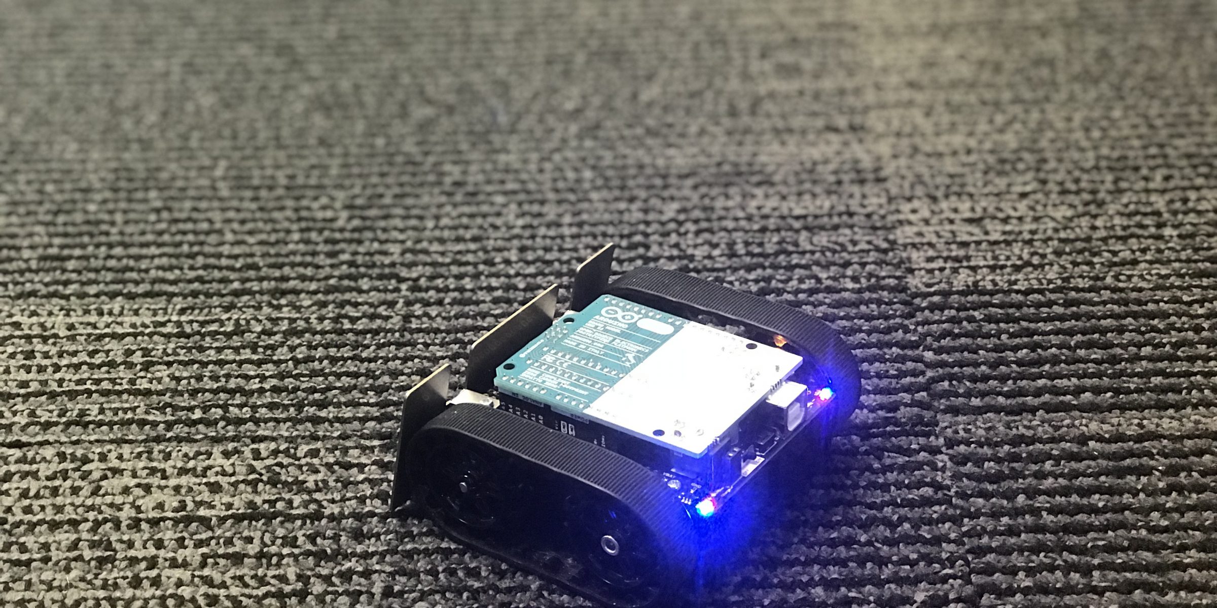
This was the case when I started working on a mini sumo robot based on the Pololu Zumo v1.2.
The chassis is complete with independent left and right motors with silicone tracks, and a suite of sensors including an array of infrared reflectance sensors, a buzzer, a 3-axis accelerometer, magnetometer, and gyroscope. The robot’s control interface uses a pin-out and footprint compatible with Arduino Uno-like microcontrollers. This is super convenient, because I can use any Arduino Uno compatible board, plug it into the robot, and be ready to go. But the Arduino Uno is an AVR, and there isn’t a readily available Ada 2012 compiler for AVR… back to the drawing board…
Or…
What if we could still write SPARK code and be able to compile it into some C code. Then use the Arduino compiler to compile and link this code in with the Arduino BSPs and runtimes? This would be ideal because I wouldn’t need to worry about writing a BSP for the board I am using, and I would only have to focus on the application layer. And I can use SPARK! Luckily, AdaCore has a solution for exactly this!
CCG to the rescue!
The Common Code Generator, or CCG, was developed to solve the issue where an Ada compiler is not available for a specific architecture, but a C compiler is readily available. This is the case for architectures like AVR, PIC, Renesas, and specialized DSPs from companies like TI and Analog Devices. CCG can take your Ada or SPARK code, and “compile” it to a format that the manufacturer’s supplied C compiler can understand. With this technology, we now have all of the benefits of Ada or SPARK on any architecture. **The CCG tool is available as part of a GNATPro product subscription and is not included with the GNAT Community release.**
Note that this is not fundamentally different from what’s already happening in a compiler today. Compilation is essentially a series of translations from one language to the other, each one being used for specific optimization or analysis phase. In the case of GNAT for example the process is as follows:
The Ada code is first translated into a simplified version of Ada (called the expanded tree).
Then into the gcc tree format which is common to all gcc-supported languages.
Then into a format ideal for computing optimizations called gimple.
Then into a generic assembly language called RTL.
- And finally to the actual target assembler.
With CCG, C becomes one of these intermediate languages, with GNAT taking care of the initial compilation steps and a target compiler taking care of the final ones. One important consequence of this is that the C code is not intended to be maintainable or modified. CCG is not a translator from Ada or SPARK to C, it’s a compiler, or maybe half a compiler.

There are some limitations to this though, that are important to know, which are today mostly due to the fact that the technology is very young and targets a subset of Ada. Looking at the limitations more closely, they resemble the limitations imposed by the SPARK language subset on a zero-footprint runtime. I would generally use the zero-footprint runtime in an environment where the BSP and runtime were supplied by a vendor or an RTOS, so this looks like a perfect time to use CCG to develop SPARK code for an Arduino supported board using the Arduino BSP and runtime support. For a complete list of supported and unsupported constructs you can visit the CCG User’s Guide.
Another benefit I get out of this setup is that I am using the Arduino framework as a hardware abstraction layer. Because I am generating C code and pulling in Arduino library calls, theoretically, I can build my application for many processors without changing my application code. As long as the board is supported by Arduino and is pin compatible with my hardware, my application will run on it!
Abstracting the Hardware

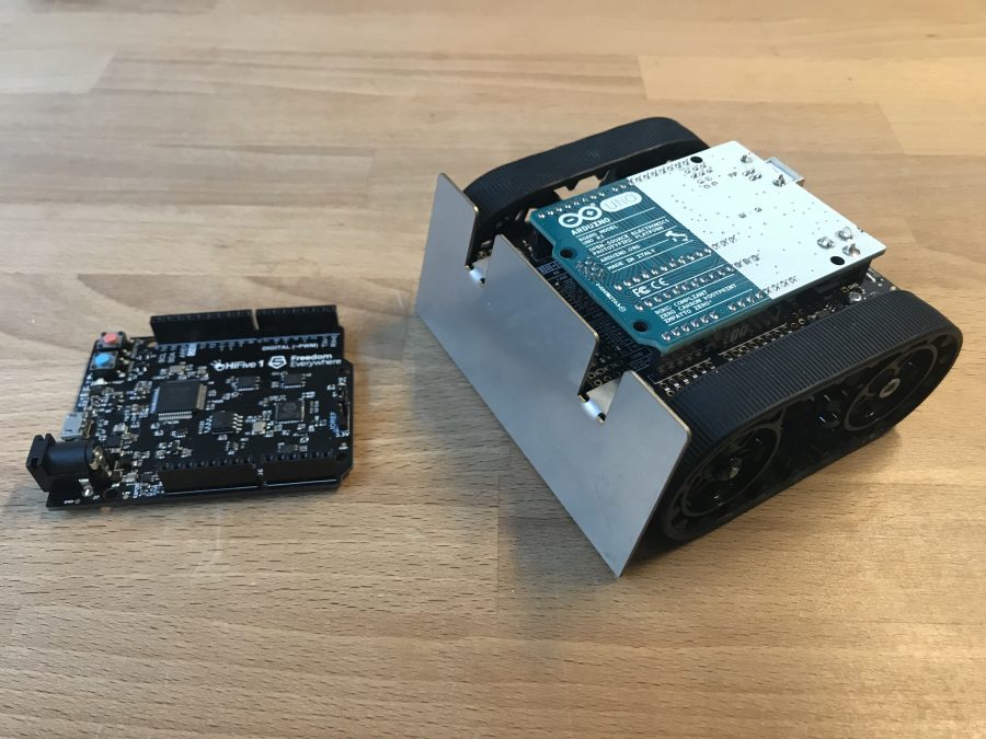
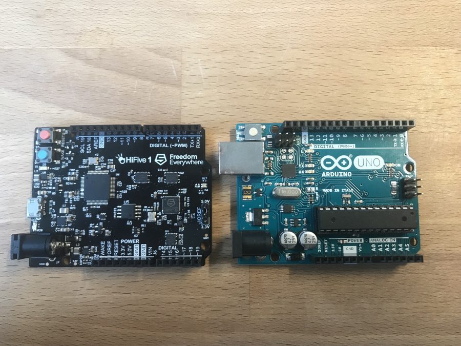
For this application I looked at targeting two different architectures, the Arduino Uno Rev 3 which has an ATmega328p on board, and a SiFive HiFive1 which has a Freedom E310 on board. These were chosen because they are pin compatible but are massively different from the software perspective. The ATmega328p is a 16 bit AVR and the Freedom E310 is a 32 bit RISC-V. The system word size isn’t even the same! The source code for the project is located here.
In order to abstract the hardware differences away, two steps had to be taken:
- I used a target configuration file to tell the CCG tool how to represent data sizes during the code generation. By default, CCG assumes word sizes based on the default for the host OS. To compile for the 16 bit AVR, I used the target.atp file located in the base directory to inform the tool about the layout of the hardware. The configuration file looks like this:
- The bsp folder contains all of the differences between the two boards that were necessary to separate out. This is also where the Arduino runtime calls were pulled into the Ada code. For example, in bsp/wire.ads you can see many pragma Import calls used to bring in the Arduino I2C calls located in wire.h.
Bits_BE                       0
Bits_Per_Unit                 8
Bits_Per_Word                16
Bytes_BE                      0
Char_Size                     8
Double_Float_Alignment        0
Double_Scalar_Alignment       0
Double_Size                  32
Float_Size                   32
Float_Words_BE                0
Int_Size                     16
Long_Double_Size             32
Long_Long_Size               64
Long_Size                    32
Maximum_Alignment            16
Max_Unaligned_Field          64
Pointer_Size                 32
Short_Enums                   0
Short_Size                   16
Strict_Alignment              0
System_Allocator_Alignment   16
Wchar_T_Size                 16
Words_BE                      0
float         15  I  32  32
double 15 I 32 32In order to tell the project which version of these files to use during the compilation, I created a scenario variable in the main project, zumo.gpr
type Board_Type is ("uno", "hifive");
Board : Board_Type := external ("board", "hifive");

Common_Sources := ("src/**", "bsp/");
Target_Sources := "";
case Board is
   when "uno" =>
      Target_Sources := "bsp/atmega328p";
   when "hifive" =>
      Target_Sources := "bsp/freedom_e310-G000";
end case;

for Source_Dirs use Common_Sources & Target_Sources;
Software Design
Interaction with Arduino Sketch
A typical Arduino application exposes two functions to the developer through the sketch file: setup and loop. The developer would fill in the setup function with all of the code that should be run once at start-up, and then populates the loop function with the actual application programming. During the Arduino compilation, these two functions get pre-processed and wrapped into a main generated by the Arduino runtime. More information about the Arduino build process can be found here.
Because we are using the Arduino runtime we cannot have the actual main entry point for the application in the Ada code (the Arduino pre-processor generates this for us). Instead, we have an Arduino sketch file called SPARKZumo.ino which has the typical Arduino setup() and loop() functions. From setup() we need to initialize the Ada environment by calling the function generated by the Ada binder, sparkzumoinit(). Then, we can call whatever setup sequence we want.
CCG maps Ada package and subprogram namespacing into C-like namespacing, so package.subprogram in Ada would become package__subprogram() in C. The setup function we are calling in the sketch is sparkzumo.setup in Ada, which becomes sparkzumo__setup() after CCG generates the files. The loop function we are calling in the sketch is sparkzumo.workloop in Ada, which becomes sparkzumo__workloop().
Handling Exceptions
Even though we are generating C code from Ada, the CCG tool can still expand the Ada code to include many of the compiler generated checks associated with Ada code before generating the C code. This is very cool because we still have much of the power of the Ada language even though we are compiling to C.
If any of these checks fail at runtime, the __gnat_last_chance_handler is called. The CCG system supplies a definition for what this function should look like, but leaves the implementation up to the developer. For this application, I put the handler implementation in the sketch file, but am calling back into the Ada code from the sketch to perform more actions (like blink LEDs and shut down the motors). If there is a range check failure, or a buffer overflow, or something similar, my __gnat_last_chance_handler will dump some information to the serial port then call back into the Ada code to shut down the motors, and flash an LED on an infinite loop. We should never need this mechanism because since we are using SPARK in this application, we should be able to prove that none of these will ever occur!
Standard.h file
The minimal runtime that does come with the CCG tool can be found in the installation directory under the adalib folder. Here you will find the C versions of the Ada runtimes files that you would typically find in the adainclude directory.
The important file to know about here is the standard.h file. This is the main C header file that will allow you to map Ada to C constructs. For instance, this header file defines the fatptr construct used under Ada arrays and strings, and other integral types like Natural, Positive, and Boolean.
You can and should modify this file to fit within your build environment. For my application, I have included the Arduino.h at the top to bring in the Arduino type system and constructs. Because the Arduino framework defines things like Booleans, I have commented out the versions defined in the standard.h file so that I am consistent with the rest of the Arduino runtime. You can find the edited version of the standard.h file for this project in the src directory.
Drivers
For the application to interact with all of the sensors available on the robot, we need a layer between the runtime and BSP, and the algorithms. The src/drivers directory contains all of the code necessary to communicate with the sensors and motors. Most of the initial source code for this section was a direct port from the zumo-shield library that was originally written in C++. After porting to Ada, the code was modified to be more robust by refactoring and adding SPARK contracts.
Algorithms
Even though this is a sumo robot, I decided to start with a line follower algorithm for the proof of concept. The source code for the line follower algorithm can be found in src/algos/line_finder. The algorithm was originally a direct port of the Line Follow example in the zumo-shield examples repo.
The C++ version of this algorithm worked ok but wasn’t really able to handle occasions where the line was lost, or the robot came to a fork, or an intersection. After refactoring and adding SPARK features, I added a detection lookup so that the robot could determine what type of environment the sensors were looking at. The choices are: Lost (meaning no line is found), Online (meaning there’s a single line), Fork (two lines diverge), BranchLeft (left turn), BranchRight (right turn), Perpendicular intersection (make a decision to go left or right), or Unknown (no clue what to do, let’s keep doing what we were doing and see what happens next). After detecting a change in state, the robot would make a decision like turn left, or turn right to follow a new line. If the robot was in a Lost state, it would go into a “re-finding” algorithm where it would start to do progressively larger circles.
This algorithm worked ok as well, but was a little strange. Occasionally, the robot would decide to change direction in the middle of a line, or start to take a branch and turn back the other way. The reason for this was that the robot was detecting spurious changes in state and reacting to them instantaneously. We can call this state noise. In order to minimize this state noise, I added a state low-pass filter using a geometric graph filter.
The Geometric Graph Filter

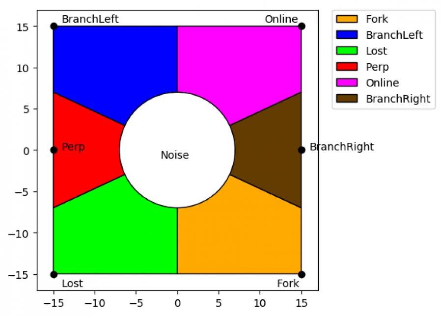
If you ask a mathematician they will probably tell you there’s a better way to filter discrete states than this, but this method worked for me! Lets picture mapping 6 points corresponding to the 6 detection states onto a 2d graph, spacing them out evenly along the perimeter of a square. Now, let’s say we have a moving window average with X positions. Each time we get a state reading from the sensors we look up the corresponding coordinate for that state in the graph and add the coordinate to the window. For instance, if we detect a Online state our corresponding coordinate is (15, 15). If we detect a Perpendicular state our coordinate is (-15, 0). And so on. If we average over the window we will end up with a coordinate somewhere in the inside of the square. If we then section off the area of the square into sections, and assign each section to map to the corresponding state, we will then find that our average is sitting in one of those sections that maps to one of our states.
For an example, let’s assume our window is 5 states wide and we have detected the following list of states (BranchLeft, BranchLeft, Online, BranchLeft, Lost). If we map these to coordinates we get the following window: ((-15, 15), (-15, 15), (15, 15), (-15, 15), (-15, -15)). When we average these coordinates in the window we get a point with the coordinates (-9, 9). If we look at our lookup table we can see that this coordinate is in the BranchLeft polygon.
One issue that comes up here is that when the average point moves closer to the center of the graph, there’s high state entropy, meaning our state can change more rapidly and noise has a higher effect. To solve this, we can hold on to the previous calculated state, and if the new calculated state is somewhere in the center of the graph, we throw away the new calculation and pass along the previous calculation. We don’t purge the average window though so that if we get enough of one state, the average point can eventually migrate out to that section of the graph.
To avoid having to calculate this geometry every time we get a new state, I generated a lookup table which maps every point in the polygon to a state. All we have to do is calculate the average in the window and do the lookup at runtime. There are some python scripts that are used to generate most of the src/algos/line_finder/geo_filter.ads file. This script also generates a visual of the graph. For more information on these scripts, see part #2 of this blog post! One issue that I ran into was that I had to use a very small graph which decreased my ability to filter. This is because the amount of RAM I had available on the Arduino Uno was very small. The larger the graph, the larger the lookup table, the more RAM I needed.
There are a few modifications to this technique that could be done to make it more accurate and more fair. Using a square and only 2 dimensions to map all the states means that the distance between any two states is different than the distance between any other 2 states. For example, it’s easier to switch between BranchLeft and Online than it is to switch between BranchLeft and Fork. For the proof of concept this technique worked well though.
Future Activity
The code still needs a bit of work to get the IMU sensors up and going. We have another project called the Certyflie which has all of the gimbal calculations to synthesize roll, pitch, and yaw data from an IMU. The Arduino Uno is a bit too weak to perform these calculations properly. One issue is that there is no floating point unit on the AVR. The RISC-V has an FPU and is much more powerful. One option is to add a bluetooth transceiver to the robot and send the IMU data back to a terminal on a laptop for synthesization.
Another issue that came up during this development is that the HiFive board uses level shifters on all of the GPIO lines. The level shifters use internal pull-ups which means that the processor cannot read the reflectance sensors. The reflectance sensor is actually just a capacitor that is discharged when light hits the substrate. So to read the sensor we need to pull the GPIO line high to charge the capacitor then pull it low and read the amount of time it takes to discharge. This will tell us how much light is hitting the sensor. Since the HiFive has the pull ups on the GPIO lines, we can’t pull the line low to read the sensor. Instead we are always charging the sensor. More information about this process can be found on the IR sensor manufacturer’s website under How It Works.
There will be a second post coming soon, which will describe how to actually build this crazy project. There I detail the development of the GPS plugin that I used to build everything and flash the board. As always, the code for the entire project is available here: https://github.com/Robert-Tice/SPARKZumo
Happy Hacking!
