Make with Ada 2020: The SmartBase - IoT Adjustable Bed
by Emma Adby –
John Singleton's The SmartBase - IoT Adjustable Bed won both the first prize and a finalist prize in the Make with Ada 2019/20 competition. This project was originally posted on Hackster.io here.
Story
My wife suffers from a rare condition that causes her to be nauseous for many hours quite often. Through trial and error, she has learned that one thing that seems to alleviate the symptoms is sitting upright and perfectly still. I noticed that often, early in the morning, she would slip out of bed and move to the couch where she can sit upright while I slept in bed.
So, about a year ago, after too many nights of being uncomfortable with our bed, my wife and I decided to finally go bed shopping for a good mattress. In doing so we realized how common it is now that people purchase adjustable bases with their mattresses. It dawned on us that having an adjustable base would be excellent for her condition as she could sit up in bed whenever she needed and she wouldn’t have to go to the couch to do it. After trying one on a showroom floor we were excited to find that we loved it and we went out and bought one with our new mattress.
At first, it was amazing; being able to prop yourself up in bed. But then there were problems. When my wife wanted to raise the bed, if I wasn’t there she’d have to fumble around for the remote (which always seemed to be hard to find). Often, if she wasn’t feeling well, she’d give up and acquiesce to laying supine. Another problem we had was that we tended to fall asleep with the bed in the upright position. This gets quite uncomfortable for the entire night and the effort needed to find the remote and adjust the bed would wake us from our sleep, making it hard to get back to sleep.
One night, when faced with this problem it dawned on me: we already use our Alexa to control our lights and other devices, why not our bed? A quick Google search revealed that nothing like this had ever been done. To make it worse, adjustable beds are primitive affairs --- they don’t have APIs and they aren’t programmable. They rely on power control circuits to drive them.
This seemed like the perfect type of project to take on. At the time, I had recently completed my Ph.D. in Computer Science where I focused on formal methods and new techniques for specification inference. From this experience I was already familiar with Ada and SPARK, which uses a specification language similar to my advisor’s own JML. Although I knew about Ada through this experience (The Building High Integrity Applications with SPARK book was one of the first I stole from my advisor’s office!) I hadn’t made anything “real” in Ada, so I thought I’d do this also as a way of understanding what the state of Ada/SPARK would be for a real product.
Project Goals and Overview
The goals of this project were to create an IoT device that was:
- Able to control the movement of a wired adjustable bed.
- Able to be easily reconfigured to work with other wired adjustable beds.
- Able to be controlled by both an Amazon Alexa device as well as the original remote.
- Able to sense occupancy in the room and able to produce under bed safety lighting when walking around at night.
- Written in Ada/SPARK 2012.
- Nicely designed in terms of fit and finish (since I planned on actually using it!). That means that the entire system should use its own custom PCBs and be hosted inside of a custom-designed case that would look great under my bed.
To explain the product, I’ve prepared two videos that demonstrate the main features of the SmartBase as well as showcase its physical construction.
My wife was more than happy to demo the SmartBase for the purposes of this contest.
Example of the startup sequence for bed and having the safety lighting activated.
For the interested reader, you can read the remainder of this document to learn all about the different phases of development for this project. Roughly, the phases of development this project followed were:
1. Reverse engineering, in which I figure out how to control the bed.
2. Prototyping, in which I made some rough perf-board prototypes.
3. PCB design, because no one wants a rats nest of wires under their bed, I designed a series of PCBs to support the function of the SmartBase.
4. Enclosure Design, in which I designed a case for my project.
5. Software Design, which essentially happened at all phases, but I’ve given it its own section here.
6. Verifying Things, in which I do a little bit of verification.
7. Moving to STM32, in which I describe porting the entire project over to a STM32F429ZIT6 and a ESP32 for the WIFI functionality.
8. Bitbanging a WS2812B on a STM32F4 in Ada. Neopixels are only easy to use if you are using an Arduino. Apparently no one had done this one before, so, armed with an oscilloscope and a ARM manual, I figured out how to make that happen.
9. Wrapup, What did I think about using Ada to build the SmartBase?
For the complete code of the SmartBase running on the RPIZeroW, please visit: https://github.com/jsinglet/sm...
For the complete code of the STM32 version of the SmartBase please see this repository: https://github.com/jsinglet/smartbase-stm -- This repo is essentially a fork of the above repository which targets the STM32. I've published them separately so it's easy to understand which repository represents which product.
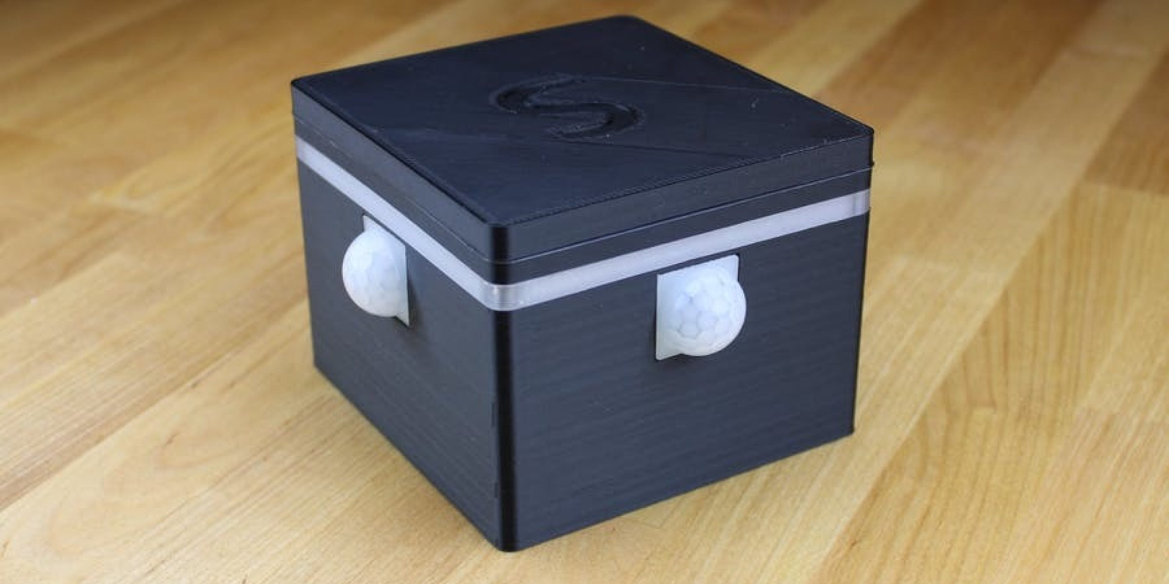
However, before we jump into all that, here are some pictures of the finished project in action. I hope you enjoy reading about it as much as I enjoyed making it!


 and headers.")


Phase 1: Reverse Engineering
The first problem I had to solve was: how do I control the adjustable base? As I’ve mentioned, I’m a software guy, but I’m dangerous with a multimeter. To figure this out, I simply started by sliding under my bed and looking at how it currently functioned.
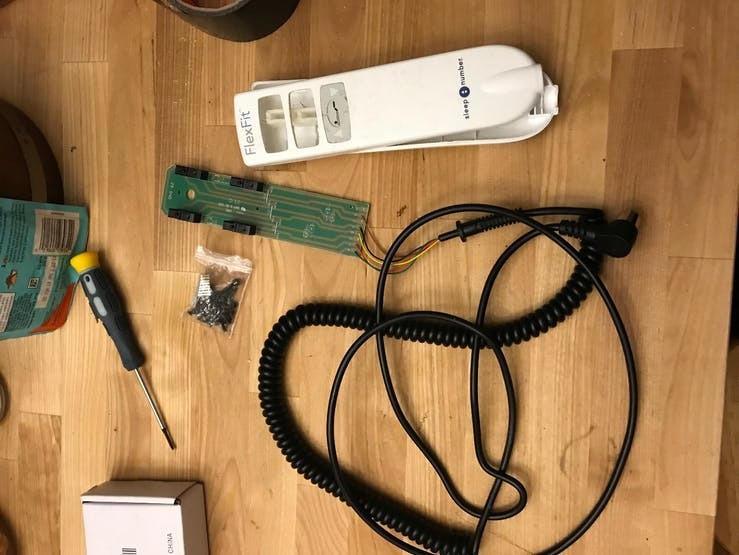
The configuration of my bed was that of a wired remote, connected with a DIN5-style (big round connector commonly found in MIDI applications). Again, being a software guy, I assumed that perhaps the way the people who built the bed constructed it was to perhaps to implement some sort of protocol over serial. I connected it to my computer, fired up WireShark, but alas, nothing sensible came out of the remote.
So of course, my next step was to disassemble the remote. The wired remote, horrifically disassembled, is pictured below.
After some experimentation with a multimeter I was able to determine that the circuit was quite simple. Here’s a picture of a whiteboard from around the time I was figuring it all out:
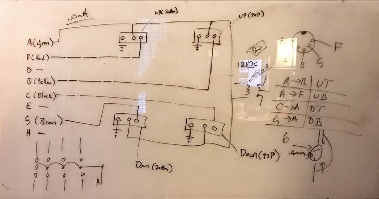
The logic for the circuit is actually quite simple. One of the 5 pins functions as the power, which happens to be +30V. The other pins are connected to the power via a switch and fed back into the bed. I tested the idea by taking hookup wire and touching it across the various pins in the configuration I had determined through my schematic analysis and sure enough it worked. With this information, I was ready to construct a rough physical prototype.
Phase 2: The Super Rough Prototype
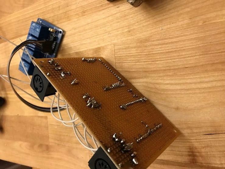
So after learning the basics of how the control circuit worked, I wanted to test if this could be controlled via relays so after a few trips to my local electronics hacking store SkyCraft (a really one of a kind place!) and some Amazon purchases I managed to put together a rough perfboard prototype, which sadly I didn’t take a picture of when it was all together – however, I saved the board, which is pictured connected to a off the shelf relay module, below:
Phase 3: Moving from Perfboard to PCB
One of my goals for this project was to have a tidy little box I could stick under my bed that my wife would tolerate. The early perfboard prototype sat on top of some roughly cut tile with a lot of duct tape. I don't have a picture, but it was a great sight. Horrifying, but a good sight.
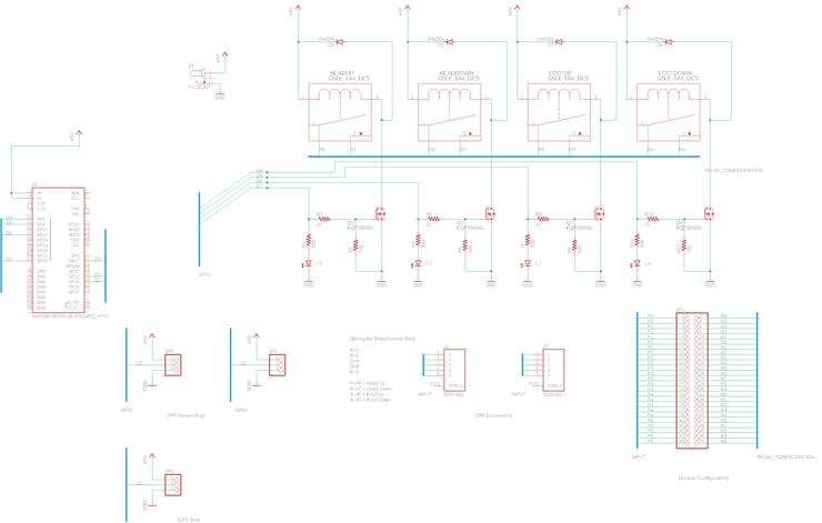
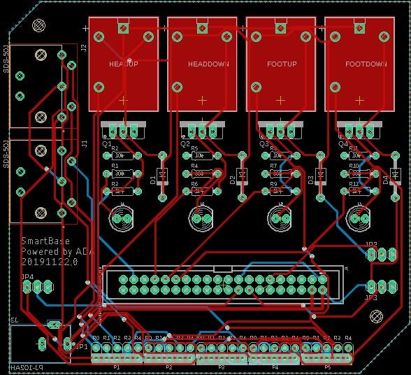
If I was going to have a permanent fixture, I had to fix the ratsnest problem, starting with the circuit. For this, I decided to start by designing my own custom PCB to control the bed. The topic of how many wrong turns and iterations of the PCB I did could frankly fill many pages. To shorten that, I'll just present my finished schematics, below. Before that, however, let me just say that I used JLCPCB to do all my fabrication, including SMT part placement. I can't say enough good things about this company. They are fast, cost effective, and the boards are flawless. For my PCB layout I used Autodesk Eagle, which was great as well.
To gain a better understanding of the hardware required to run the SmartBase, I've prepared the following Block Definition Diagram which details the main systems the SmartBase relies on to provide its functionality.
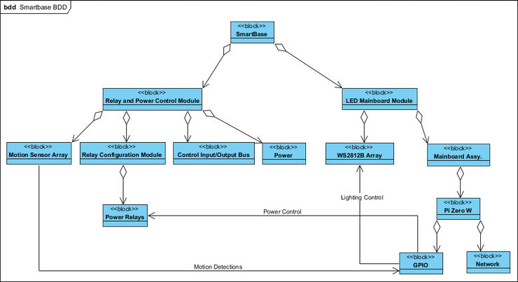
At the top level we have the Relay and Power Control Module and the LED Mainboard Module. These two components roughly outline the two boards that were created for this project. In the following paragraphs we discuss each board separately.
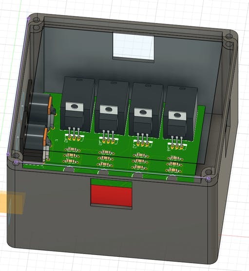
First, let's look at the board on the bottom, which was responsible for power and hosting the relays on the board that control the bed.
Power is routed in through this board on the bottom through a barrel connector to all of the components within the SmartBase. Other components hosted on this board are:
- The PIR Motion Sensors, via Amazon
- 5V DC Relays, via Digi-Key
- Logic Level MOSFET transistors, via Digi-Key
- 2 DIN 5 Connectors, via Digi-Key
- Various LEDs, diodes, and resistors that I sourced at SkyCraft.
In order to control the relays (safely) with GPIO signals I used a series of FQP30N06L "logic level" MOSFET transistors connected as shown in the above schematic.
One cool thing I did was make the configuration of the relays jumpered, so if I ever encountered a different bed with a different control configuration they relays can be easily rerouted. The basic idea is that the jumper positions control which pin gets the power signal when the relay is activated.
Next, this is the top board, which hosts the WS2812B LED array as well as the CPU, which is a Raspberry Pi Zero W. The schematic and the layout file for the board is pictured, below:
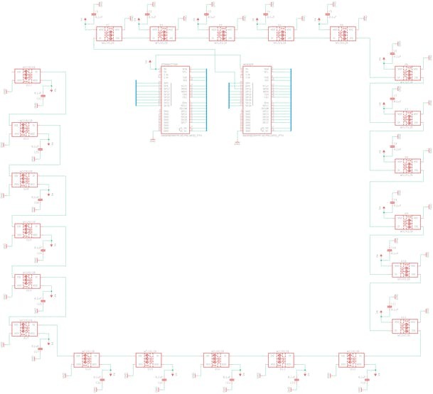
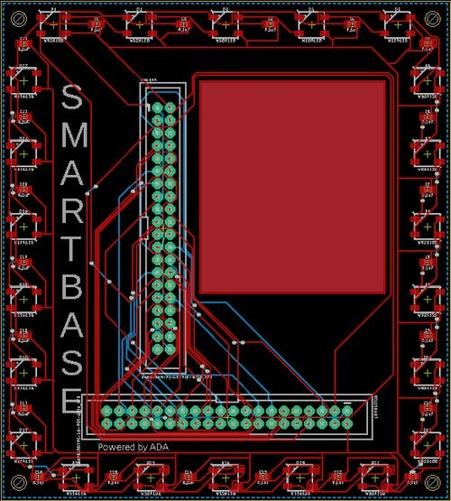
This board hosts two 40 connectors which host both the GPIO cable connector from the bottom board and the header for the Raspberry Pi itself. If you can believe it, I got this board right on the first try just by following manufacturer spec sheets.
Phase 4: Enclosure Design
Printing the top of the SmartBase.
To build the enclosure I opted for a very simple design, which features several components:
- Two DIN-5 ports on the back. One connects to the bed and the other allows you to reconnect the remote control to the bed if you wish to ever manually control the bed. In reality I never used this feature because the voice control was so good.
- One power connector for 5VDC power.
- The case actually splits into 3 different bodies. The bottom body, the top body, and the "lens" which I printed out of clear PETG. The rest of the case was printed in black PLA.

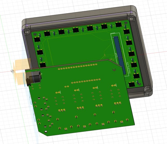
One challenging aspect of this case design was actually coming up with appropriate screw sizes. I ended up using a combination of M2 and M3 screws. I found a bunch of assorted hex head sizes on amazon and was able to design the case dimensions around those.
Phase 5: Software Design
In this section we will discuss the design of the Ada software that runs the SmartBase. The software described in this section is the software that drives the version of the SmartBase shown in the demo. Later in the section on STM32 we discuss how these components are handled on a STM32F4-family processor in Ada. However, before we start, a few notes:
- SmartBase makes use of tasking. It is in fact mainly composed of 5 core tasks that handle relay control, command interfacing, MQTT command processing, and LED status control.
- Because I wanted to be able to verify things (and the run it on metal later), I enabled the Ravenscar profile.
- Portions of the application are written in Spark. Notably the components that control the bed are written in Spark with some lightweight specifications around the control sequences.
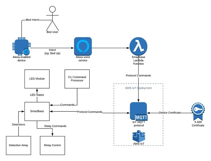
Concept of Operation
The SmartBase gets inputs from PIR sensors which will trigger fade on / fade off events. These events are able to be processed along with MQTT events which arrive via a AWS Lambda function connected to the Alexa voice service. These MQTT events then turn into motion of the bed via the relay control subsystem. The following diagram provides a high level summary of how the SmartBase performs its main operations.
Tasking
The typical way one builds microcontroller applications is via a state machine pattern encoded into the main loop of the program running on the microcontroller.
For simple applications this is generally fine but for more complex applications it is common to use the multi-tasking capabilities found in an RTOS such as FreeRTOS. That said, one of the excellent aspects of programming a system like the SmartBase in Ada is Ada's excellent (and I mean excellent) tasking facilities that are built right into the language. Because of this, I opted to use Ada's tasking features to structure my application. If you'd like to learn more about this capability, I suggest you take a look at Fabien's article over on the AdaCore blog, here: There's a mini-RTOS in my language.
The SmartBase uses 5 tasks for performing its core operations:
1. The Bed Task, which is responsible for controlling access to the relay control system.
2. The CLI Task, which provides a debugging command-line based interface to the SmartBase.
3. The MQTT Task, which listens for protocol events from Amazon IoT (from spoken voice commands) and talks to the bed task to execute protocol events.
4. The LED Task, which is responsible for providing a structured interface to controlling the LED ring. The LED ring defines states for connecting, connected, fading on, and fading off.
5. The Motion Detector Task, which is really comprised of several tasks and is easily the most complex of the 5. I describe the Motion Detector tasks more detail later in this section.
The following diagram details the relationship of these five tasks in more detail. Note that in the diagram I use the method loop to indicate the main loop of the task. One stipulation of Ravenscar is that tasks do not exit and notation calls that restriction out.
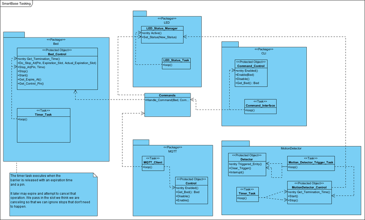
The design of the system is that all interaction with the LED and Bed components happens strictly through the Commands interface with the exception of the Motion Detector tasks. This interface itself in turn only acts with protected objects. For example, if a command arrives via the command line and the MQTT task at the same time (assuming we have more than one CPU) they will both attempt to process the command through the Commands interface which in turn will ensure the access to the resources is serialized.
One interesting task is the LED_Status_Task, which is responsible for processing changes to the LED status ring. There are two problems solved in this component: 1) How to provided serialized access to the underling LED hardware and 2) How to ensure that transitions to different LED states are valid? The first problem is solved through protected objects. The second part of the program is covered in more detail in the next section on verification.
Lastly, the most complicated use of tasking is easily in the way the SmartBase does motion detection. As can be seen in the above figure, the MotionDetector package is composed of two Tasks and two protected objects. They function in the following fashion:
- Interrupts arrive on the protected object
Detector, which very quickly sets an interrupt flag. - The
Motion_Detector_Trigger_Taskmonitors this flag by waiting on the entry toTriggered_Entry. Once the barrier releases, theMotion_Detector_Trigger_Taskengages theTimer_Taskvia theMotionDetector_Controlobject's Start method. - The
Timer_Taskis then responsible for changing the status of the LED ring to OFF once the detection is finished. - Re-triggering is handled at the level of the
Motion_Detector_Trigger_Task. If the LED hasn't already faded off, more time is simply added to the timeout. That way, if people keep moving the lights remain on.
Other Software Details
Some other items worth mentioning pertaining to the Pi Zero version of this implementation are the following:
- For MQTT I wrote C bindings to the Eclipse Paho library. On the STM32 platform, I use the MQTT AT interface directly built into the ESP32 and program it over UART.
- For LED Control on the Pi I used a neopixel library and bound to it in C. On STM32 there is no such type of library for Ada (or anything else, really) so I wrote my own hand-coded bit-banged version of a WS2812B control library. What is nice about my implementation is that it is optimized for my particular use case and uses constant RAM (whereas other implementations use RAM on the order of the number of pixels in the array). You can read about it in the section on STM32.
- I did all my work in GPS, but I would really like to get my hands on the Eclipse version of the GNAT tool set and would happily accept any complimentary licenses!
Phase 6: Verifying Things
One of my goals was to check out the specification-related features of Ada with this project. To that end, I came up with two small verification tasks for my project.
1. First, rather than use a timer, part of the way that the bed is controlled is through the use of tasks and protected bodies. These tasks use a barrier to control when a task should start waiting to see if it should stop moving the bed. One aspect of this protocol is that since other commands may be received while the bed is moving (thus, nullifying the current action), the tasks controlling the timeout have to know that they have been cancelled without having race conditions around the starting and stopping of the bed. I will show a little bit of what I did in the protocol with relation to specification.
2. Second, a critical element of this application is the LED status ring. In this application the LED status ring is used for indicating when the SmartBase is connecting to the internet, disconnected, and when motion is detected. Designing a system that can process all of these states at any time is trickier than it sounds and I discuss the model I used for managing the LED status ring.
Specifications on the Bed Controller
The first thing I wanted to write some specifications for were the behaviors surrounding the behavior of the stopping and starting of the bed. As I described earlier. To do this I wrote the following specifications, which I will explain after the listing.
procedure Do_Stop_At (Pin : in out Pin_Type;
                      Expiration_Slot : Time;
                      Actual_Expiration_Slot : Time)
  with
    Contract_Cases => (
        -- the slots match. This means
        -- we will be performing the action
        -- on the pin we expected.
        (Actual_Expiration_Slot = Expiration_Slot) => Pin'Old = Pin,
        -- the slots DON'T match, which means we missed our window
        (Actual_Expiration_Slot /= Expiration_Slot) => Pin = Pin_None
    );

procedure Stop_At (Pin : in out Pin_Type; Expiration_Slot : Time);

procedure Stop
  with
    Global => (Input => (Device.GPIO),
    Output => (Bed_State_Ghost.Moving)),
        Pre  => True,
        Post => Bed_State_Ghost.Moving = False;
In the first specification, there are two cases. The first case is when the time slot that the timer task used to cancel the task is the one currently executing. In this case, we expect that the pre-state value of the Pin matches the post-state value of the pin, that is, we actually perform the stop on the pin we expected to. In the second case we require that if they are not the same that no pin is used to do anything. This is represented by the expression Pin = Pin_None.
The second set of specs are on the Stop and Start methods. These specs simply require that, in the case of Stop, we actually stop the bed, and in the case of Start, we assign a pin when the move was successful.
In the above listing, you might note that I am using an explicit Ghost package to hold ghost state. Why am I doing this when Ada/Spark 2012 has this feature built in? This is to get around an incompatibility I was having getting this to run on the Raspberry Pi, which only had an older version of GNAT available (and didn't support ghost fields). I was able to replicate this behavior by just encoding the ghost state into an actual package. Since ghosts are really just syntactic sugar for that it works quite nicely.
Design of LED Status Control Ring State Machine
Of course, verifying things doesn't always mean you write specifications. There are lots of ways to add more assurance around your design. The next thing I decided to analyze was the LED status ring, the states for which can be seen in the following diagram.
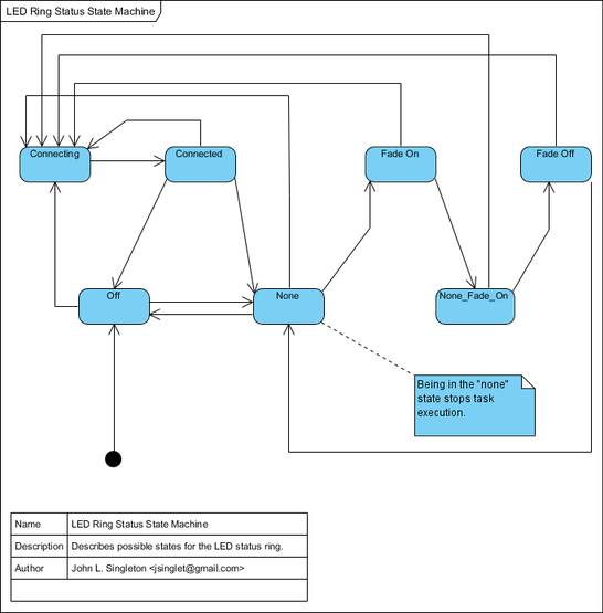
In the above diagram we have all of the states that the LED ring can be in. One thing that was important to me was ensuring that, the following properties would hold:
- When the LED faded ON, the system would not attempt to fade it back on. It sounds like a simple thing, but I didn't want to create a disco effect.
- I wanted to ensure that no matter what state the system was in, if the connection was every lost the system would, as soon as it could, notify the user. This point is subtle. I didn't want the system to interrupt the visual effect of a fade, however I did want the connection sequence to begin as soon as possible. Ensuring this sort of separation was critical to my design.
- Once the system was trying to connect, the visual feedback that the system was connecting should not be interrupted, even if motion detection events are happening. In my design, one doesn't have to disable motion detection -- the state machine of the LED ring simply subsumes this logic and makes such interruptions impossible.
What's nice about having a model like the one pictured above is that we can simply look at it and see if the desired properties hold. So let's do that one by one.
The first property obviously holds. Specifically, the only edges going into Fade On come from None, which is not reachable for any state after Fade on. So far so good.
The second property holds because all states in the state machine may make a transition to Connecting after completing their state transition.
The third property holds because for all nodes in the graph there are no transitions from the Connecting state except Connected.
Phase 7: Moving to the STM32
Demo showing the STM32F429 Discovery Board driving a SmartBase control board.
As I mentioned in the introduction, after completing this project on the Raspberry Pi Zero W platform I immediately began work on a version that could run on bare metal on a STM32 processor.
For my development boards I selected:
- The STM32F429 Discovery board, via Digi-Key
- The ESP32 WIFI Evaluation board, via Digi-Key
I'm not totally done getting the SmartBase running on the STM32 platform, but here's a quick rundown of what is and isn't done so far:
- The Bed Control is done and works perfectly with the CLI interface over a serial console. You can see that demonstrated in the video, above.
- The Motion Detection is done and perfectly works with the LED array.
- The LED Controls are done, thanks to a driver for the WS2812B I wrote which I describe in detail in Section 8.
- The MQTT work is almost done. To do this I had to build a custom ESP32 firmware to enable the MQTT AT command set on my board. This works perfectly through the serial console and I'm able to get it to pull down MQTT messages. I'm currently writing the driver that will send the AT commands over UART to the ESP32.
- PCB design hasn't been redone for the ESP32 + STM32 combo. However, I'm really excited about getting these guys onto my PCBs and I've already looked over the reference designs.
Phase 8: Bit Banging a WS2812B on a STM32F4 in Ada
Demo of the bit banging approach to controlling the WS2812B on an STM32F4 with Ada.
One of the most interesting parts of this project was when I had to get the LED array working on the STM platform in Ada. The timings on the WS2812B are relatively tight and unlike platforms like Arduino and others where there is a wealth of information available, on the STM32 basically nothing exists. What little does exist could never be used in an Ada program because it is hopelessly coupled to the hardware abstraction layers and drivers provided by ST Microelectronics. Therefore, to do this I had to start from from principles and work my way forward.
From the manufacturer specification sheets, the WS2812B implements the following protocol:
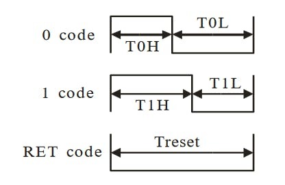
To trick to producing colors with the WS2812B is to set the rightmost 24 bits of a number to the GRB value you want to set. For example, to set a LED to green, you would send a waveform corresponding to the following number:
0000 0000 1111 11111 0000 0000 0000 0000
      (white)      (green)          (red)          (blue)
To control multiple pixels you just repeat this for as many pixels as you have, making sure to say within the Treset window, which practically just means you do it as fast as possible.
To get reliable timings the codes that drive the WS2812B must be written in assembly with interrupts disabled. As a proof of concept I decided to build up a basic loop to set a single LED to green. To do this I cross referenced the cycle cost for each of the instructions, which can be found on the ARM website
As for how many instructions are required, the calculations were performed as follows:
The STM32F429ZIT6 operates at 180Mhz, i.e. 180000000 CPS, which means each cycle costs: 0.00555555556 microseconds (5.555555559999999 ns). To achieve 800ns we need 800/5.555555559999999 = 143.9 instructions (i.e., 144) of delay time added to the pipeline. This works out to 144 * 5.55ns = 799.2 ns, which is well within the +/- 150ns needed. Similarly, to achieve 450 ns, we need 450/5.555555559999999 = 81 instructions of delay added. That gives us 81 * 5.55ns = 449.55, which is well within +/- 150ns needed.
The trick to implementing this is to work in the time to load and set the bits high (or low) and combine that with a loop that keeps that timing in check.
From reading other codes (such as the official neopixel code), one way people have done this is by adding explicitly chains of NOP instructions to the pipeline. This works well on a 16Mhz processor like the Arduino's AVR. It doesn't work as well on a 180Mhz processor. Because I didn't want pages and pages of NOPs pasted into my program, I decided instead to work out the code using a loop structure.
The following code works essentially according to the following procedure:
1. Load up a counter that dictates the number of pixels we want to do this for.
2. Load up a number that indicates which GRB value to load.
3. Loop over each bit of the color and, following the convention above, send the appropriate bit by introducing enough cycle delay to get the required timeouts.
Initially to create this program I worked it out using the math shown above for a single color value. This worked well for a small proof of concept code, but it was difficult to scale to the entire GRB value (let alone multiple ones). To help me expand the program I used an ARM simulator that could count cycles to ensure the loops I had written were correct. I used the VisUAL simulator for this purpose.
Finally, however, I wanted to be absolutely sure that my timings were correct. I actually didn't own an oscilloscope so I finally broke down and ordered one off of Amazon. I ended up getting a Hantek DSO5072P, which is a reasonably good scope for my purposes, if not a fancy one. The image below shows an example cursor session, measuring the delay of one bit.
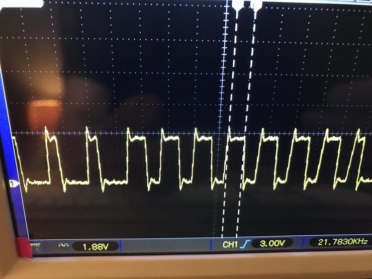
The following code shows the general principle of operation -- if you'd like to see how I implemented it in the actual Ada code, please see the end of this post for the full code. One interesting thing to note here is that most neopixel implementations consume ram that grows with the number of pixels. Because I don't ever want any pixel to be a different color than another one I was able to make a simplification that allows my program to always require constant memory, regardless of the number of pixels being driven.
For now I'm just using this library in my own project, however, if others find it useful I'd consider contributing a library that makes STM32 control of neopixels accessible to all.
cpsie	i
init
mov		r3, #2              ; the number of pixels to do this for
ldr		r1, =0xAAAAAA       ; load bits to be loaded
ldr		r5, =0x40021418     ; set r5 to the GPIOF register + 18 offset for BSRR
ldr		r6, =0x2000         ; pin 13 HIGH mask
ldr		r9, =0x20000000     ; pin 13 LOW mask
mov		r8, #1              ; we use this to test bits
send_pixel
cmp		r3, #0        ; test if we are done
beq		done          ; if we are out of pixels, finish up
mov		r4, #23       ; we are going to send 24 bits, prime it here.
sub		r3, r3, #1    ; decrement this pixel
send_bit
lsl		r2, r8, r4    ; build the mask by shifting over the number of bits we have
tst		r1, r2        ; check the mask against the bits we are loading.
bne		send_one      ; send a one
b		send_zero     ; otherwise, send a zero
;;;;;;;;;;;;;;;;;;;;;;;;;;;;;;;;;;;;;;;;;;;;;;;;;;;;;;;;;;;;;;;;;
send_one
str		r6, [r5]            ; set pin 13 HIGH
;;		delay for ~ 800ns
mov		r0, #36
delay_T1H
subs		r0, r0, #1
bne		delay_T1H
;;		end delay
str		r9, [r5]            ; set pin 13 LOW
;;		delay for ~ 450ns
mov		r0, #20
delay_T1L
subs		r0, r0, #1
bne		delay_T1L
;;		end delay
b		bit_sent
;;;;;;;;;;;;;;;;;;;;;;;;;;;;;;;;;;;;;;;;;;;;;;;;;;;;;;;;;;;;;;;;;
send_zero
str		r6, [r5]            ; set pin 13 HIGH
;;		delay for ~ 400ns
mov		r0, #17
delay_T0H
subs		r0, r0, #1
bne		delay_T0H
;;		end delay
str		r9, [r5]            ; set pin 13 LOW
;;		delay for ~ 850ns
mov		r0, #38
delay_T0L
subs		r0, r0, #1
bne		delay_T0L
;;		end delay
b		bit_sent
;;;;;;;;;;;;;;;;;;;;;;;;;;;;;;;;;;;;;;;;;;;;;;;;;;;;;;;;;;;;;;;;;
bit_sent
cmp		r4, #0       ; was that the last bit?
sub		r4, r4, #1   ; otherwise, decrement our counter
beq		send_pixel   ; if so, go to the next pixel
b		send_bit     ; and send the next bit
done
cpie	i
Again, if you want to see what this all looks like when it makes it back to Ada, check out the Code Section of this project.
Wrapup
In this article I detailed the creation of a novel IoT device, the SmartBase. I described how it works, and described in detail each phase of its development.
So after all of this, what is my opinion of developing this product in Ada?
Frankly, my reaction is that I cannot even imagine doing it in another language. Even though I am quite familiar with so-called "exotic" languages like Haskell, the blunt, unapologetic efficiency of Ada, the pickiness of the compiler, the the robust, built-in support for tasking and specification were a pleasure to work with and I'm confident these features helped me to find many errors that would have otherwise potentially caused problems in my system. Some other items, in no particular order are:
- Scenarios are brilliant. Using scenarios I was able to make multiple versions of the code for SmartBase for different boards and tie it all together quite easily.
- Compared to Java and other languages, the package system of Ada, in general, makes structuring a complex application much better. I love how I can have package initialization, nest objects, and in general encapsulate functionality. I think that many people learn the OO facilities in a language like Java and walk away thinking "this is what objects are all about." The package system reminded me of the one in OCaml, which I also quite like.
- I love love love the support for separate complication. When you combine that with the package system, you have a powerful mechanism for build management.
- Having a SPARK > Prove All menu in my IDE is a beautiful thing to see.
In the future I plan to use Ada on a few more projects, for example, I wanted to make some small, battery powered WIFI LED strips. I can't think of a better language for the job.
- Access and download the project schematics here.
- Access the project code here.
- GNAT Community was used in this project, download it here.
About Emma Adby

Emma Adby is the Managing Director of AdaCore Ltd. After co-leading the global marketing team for a number of years, she now manages marketing, financial, legal and HR business operations for AdaCore’s new UK technical centre-of-excellence. Emma also works to advocate for increased adoption and wider use of the Ada and SPARK languages globally by coordinating community centric activities and resources.