Make with Ada 2020: The autonomous firetruck
by Juliana Silva –
Laboratorio Gluon's project won a finalist prize in the Make with Ada 2019/20 competition. This project was originally posted on Hackster.io here. For those interested in participating in the 2020/21 competition, registration is now open and project submissions will be accepted until Jan 31st 2021, register here.

Story
Introduction
In this project I will show you the why and the how of my idea for the MakeWithAda contest. I also made a video, which is in spanish but I subtitled it to english so all you can understand, explaining the truck structure and building.
Disclaimer for MakeWithAda contest:
All the code, images, design and videos of this contest are made by myself, except the Console library, which I made, with a friend, for the previous MakeWithAda Contest in this project. Everything else is new creation for this contest.
End Disclaimer;
The problem
With the unstoppable increase in world temperatures mainly due to Global Warming, the news of fires devastating vast areas of the rainforest and populated areas, will be the usual. We can already see them in a daily basis, and will increase in the following years if we do not stop it.
These fires worldwide, are one of the greatest dangers for many species, including the human race. But as the most dangerous specie for the world, we need to implement all we can to stop this devastation.
Also, we are experiencing one notorious development of unmanned systems, from UAVs(Unmanned Aerial Vehicle) to UGVs(Unmanned Ground Vehicle), using this technology we can develop systems that increment the effectiveness of the fire extinguishing methods.
The solution
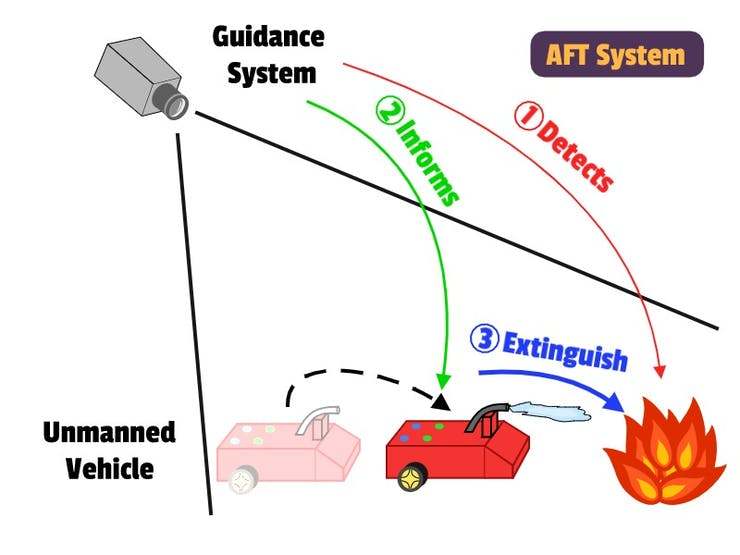
In this project I would like to introduce you AFT (the Autonomous FireTruck) which is my prototype for a solution that could be implemented in large scale, and for which the technology is already available. This proyect will consists in two main parts:
- The guidance system, which is the one that detect the position of the AFT and analyze the fire propagation and position
- The vehicle that puts out fires, which is in constant communication with the guidance system, to know exactly his own position and the fire's one.
The guidance system can be: from a mesh of antennas and sensors around the mountains, or a UAV flying over the fires, to an space satellite measuring the fire and vehicles. On the other hand, the vehicles can be anaything from an autonomous firetruck, or an autonomous airplane, or even small robots, for smaller fires.
This solution would safe life of many people and animals, directly and indirectly. Directly, by avoiding sending people to dangerous fires, and indirectly with a faster response and tireless systems that can work 24/7, increasing the efficiency of the current fire extinguishing systems.
Prototype
Since the scope of the proyect can be anywhere from a simple simulation to a fully working system, I am developing something in between. That is:
- A small guidance system which will be an image processing software running in a computer, that sends the position of the fire and the vehicle information.
- The vehicle will be a small truck that carries a small water deposit and tower to aim the waterjet.
The main reasons behind this prototype is the technology testing and the availability for a real world implementation. The guidance system (a camera detecting fire and trucks) can be mounted in poles in the forest, in an UAV or in satellites. Also, the technology in Unmanned vehicles' navigation system allow for a safe autonomous guidance that can drive them to the objective marked by the guidance system.
To sum up, this prototype tries to implement a small scale prototype of a guidance system based in image, and a small truck that actually tries to put out fires. This system can be also evolved to a real world vehicles and technologies.
The implementation
Technologies
In order to achieve our goal of a fully functional prototype we need modern hardware and software libraries. In this section I will cover the main ones I am using in this project.
OpenCV
The first one I will talk about it 'OpenCV' a computer vision and machine learning software library. It has been ported to many languages so one can use it with the one he feels more confortable. In my case I am using openCV with Python for a basic system. As I said earlier, this is not the main part of the project, so the software will be as simple as possible.
STM32f407
As the main brain on the AFT I will use the STM32F4DISCOVERY. I used this board in previous contests, and I could use some of the code that I implemented for it. Furthermore, I will keep expanding the library of drivers for this board, which will make the next projects easier to implement.
For this prototype we will be using the following interfaces of the board:
- SPI: For communication with the NRF24
- Digital I/O: For the water pump activation
- PWM: For the motors and servos.
Ada
The embedded software which will be run on the STM32 board will be programmed in Ada. I though this proyect would be a nice choice since Ada is one of the main languages in the development of critical systems, where the life of human beings are at risk. So, since this is a prototype of the software on a "real truck" or "real UAV", the use of Ada is very convenient.
Also, the use of Ada as the programming language helps in the development, detecting the most common errors and problem during developing. This makes that every release of the software is reliable with even low testing. We will be using the Ada Library so most of the interfaces of the STM32's modules are already available. However we will be implementing some library for:
- Servo control: A servo library that allows to initialize and configure the PWM port, adjust the calibration and allow for limited range of movement.
- CarControl: A library that can be used to speak with a L298N (or equivalent H-bridge) and allows to control the speed and direction.
- RF24 library: To initialize de SPI port, configure the pins, and allows for simple RF24 startup and use as a receiver.
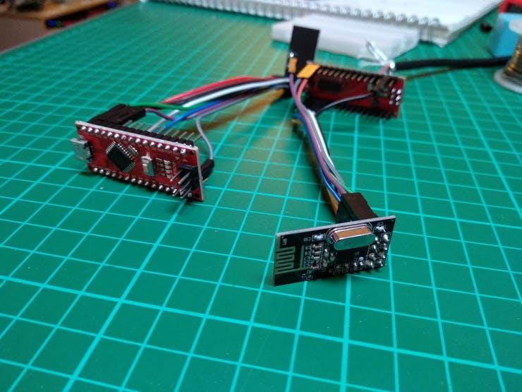
Is a cheap wireless communication module in 2.4Ghz that can be used to send and receive data. It is connected through an SPI port, and while the configuration and initiazation is a bit complex, once it is configured it is easy to use. Therefore, once this library is implemented and included in any project, the nRF24L01 module can be used seamlessly in any other project.
Guidance System
The Guidance system is the one in charge of detect the fire and its position from the vehicle, and send this information to the vehicle. Since this project is aimed for the Make With Ada Contest, I will not focus too much in this section as it is out of the scope of the contest. However, it will be fully functional, yet can be highly improved.
This system consists in two parts:
- The PC software that analyze the image from a camera
- The Arduino connected to the with the communication system attached.
The implementation of the guidance software was done in multiple iterations. I choose openCV + Python as the base, and since it was my first time with openCV I really needed several steps until I get a functional prototype. Basicly the workflow has been:
- Learn how to calibrate the camera with openCV.
- Learn how to detect simple things (in my case, colors): In this step I started detecting a color pattern in the back of the vehicle.
- Calculate the position of the vehicle from the Camera (with solvePnP function).
- Implementation of mask filtering in order to improve segmentation of colors.
- Detect background and filter constant background from the image. I have written a small tutorial, but it is in spanish
- Detect the fire/objective.
- Send all this information to the vehicle.
The Arduino software is a basic interface between the PC and the NRF24, so it basically send the data received by the USB to the NRF24.
Vehicle
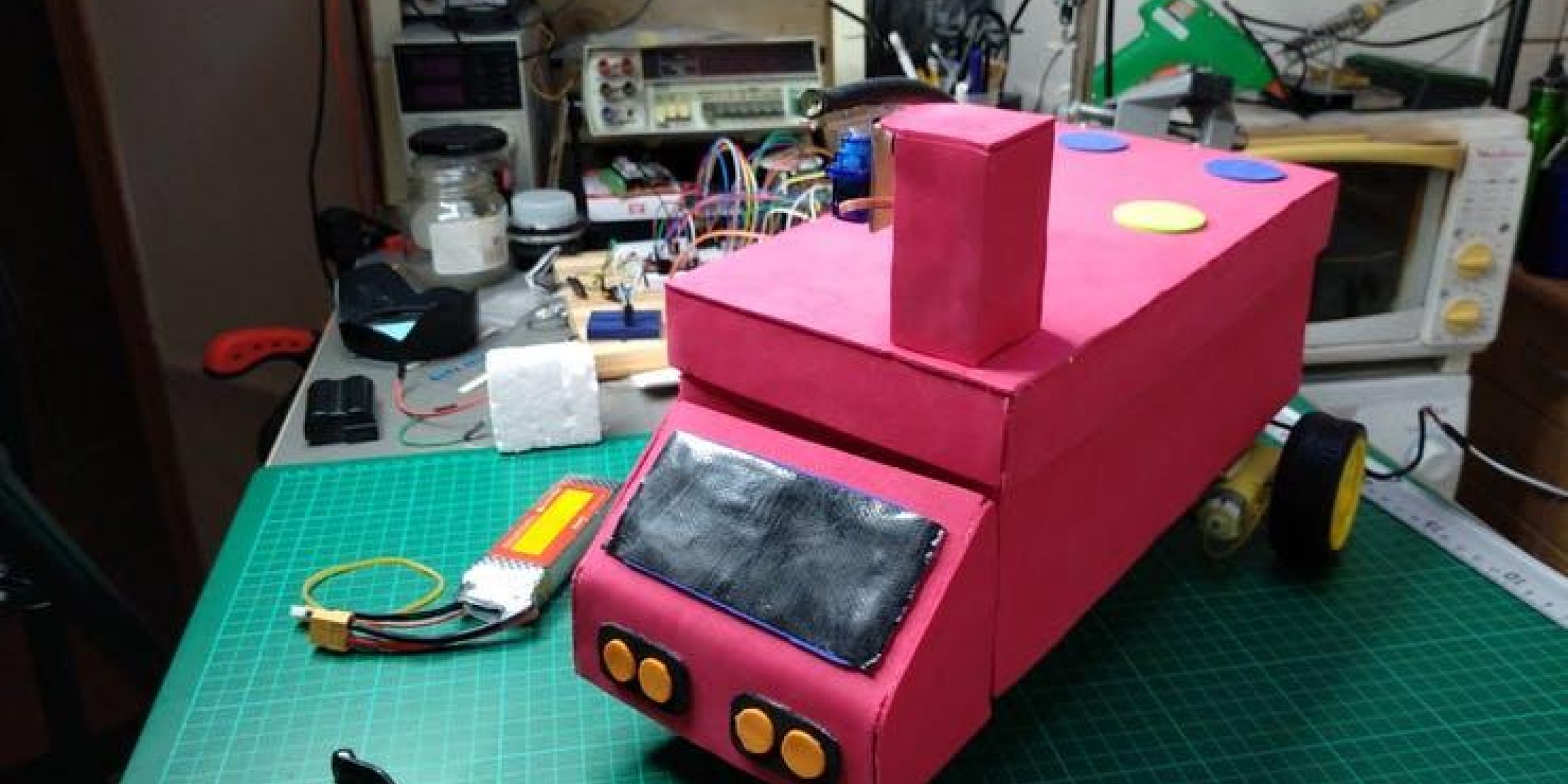
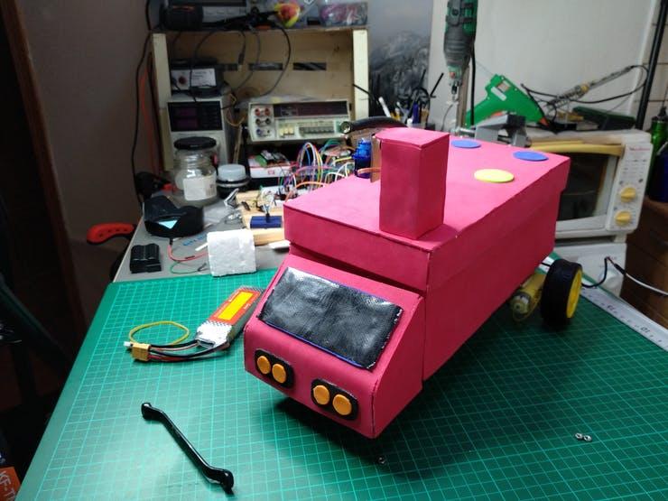
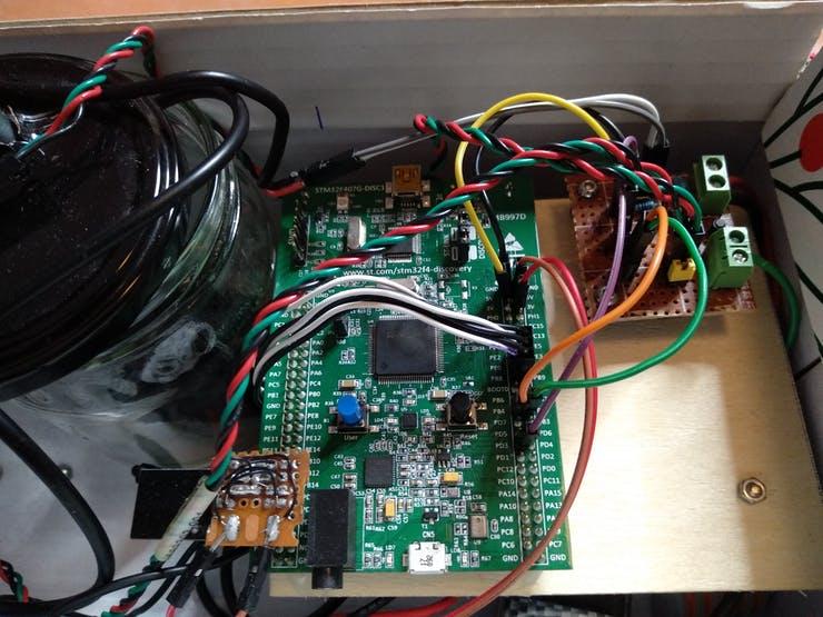
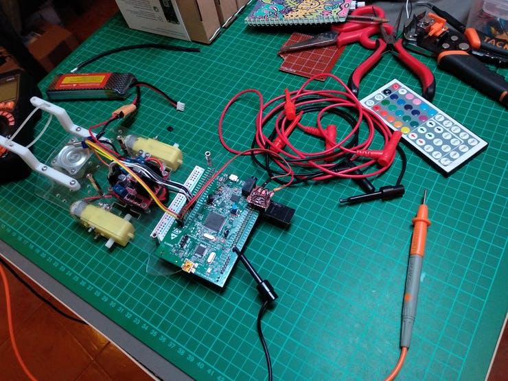
The AFT (Autonomous FireTruck) is the main part of the proyect, is the one implemented in Ada, and in where I put most of my effords. This truck is build around a cardboard box where all the components are attached. This system contains:
- A 3S-LiPo battery pack
- Two main motors with wheels
- An L298N module to control the motors.
- The STM32 as the main board of the AFT.
- A deposit with a Water Pump.
- An adaptation board for the Water Pump activation.
- Two servos for a 2 degrees of freedom control of a Hose.
- The Hose who connects the water deposit and the control tower.
Part 1 : Communications
The first part was establishing the communication between the computer and the STM32 board, so I can advance from there. With the communication link working, the next steps would be much easier. I did not found any nRF24L01 library for STM32 written in Ada, so I started working on my own version, following a little bit the interface of the Arduino's version, so it can be easily followed and upgraded. This part was a big headache, making the nRF24L01 start receiving data took me a lot of time. The nRF24L01 has a lot of configurations and registers, which makes the device hard to turn on. However, once it has been initialized it is really easy to use and intregate in any other project.

For the data in the communication I use a record to store the command type and the command data, and then I parse each binary packet received from the nRF24L01 and convert it to the Command. Then in the main loop, I update all the systems according to the new data received.
The Command types I have defined for this project were:
- TEST_LED: For testing purposes, it toggles a LED in the board so I can check that the code it is still running.
- SET_DIRECTION: Configure the CarController to set the direction of movement.
- SET_SPEED: Set the speed for the wheel of the CarController. The CarController has already the direction from the previous command.
- SET_SERVO: Sets the angle of the servos that control the hose.
- SET_PUMP: De-/Activate the water pump.
- SET_MAIN_STATUS: Currently not used, but was created in order to command different states to the truck, i.e.: STOP, MOVING_TO_TARGET, ...
- INFO_TARGET: Is used to receive the data with the position and distance of the objective.
As you would expect the TEST_LED command was the first one implemented, with this command, I started testing the communications and the full message parsing functions. Since in this prototype we are only using one way commands, with no responses, the nRF24L01 library will not implement the send functions.
In this part I learned a lot about the nRF24L01 and all the internal states and configuration, also improved my hability handling big and complex datasheets. Also, since the communication with the nRF24L01 is using the SPI interface, I learned how to use it for the first time.
About the library of the nRF24L01, it is not complete, as there are many configuration options that were out of scope for this project. However, I tried to do it as scalable as possible, with a clean and structured code.
For example to add a new register to the processing one has to:
- Define the new record and its sizes
- Create the FROM/TO unchecked Conversion
- Use the register!
Part 2: Movements
The next natural step is making it moving with the L298N and two motors. In this step I implemented the SET_DIRECTION command, which makes the car move in the desired direction. I implemented the CarController library that allows one to control a L298N board, using the digital pins to set the direction of rotation of the wheels, and a PWM signal generated to set the speed of rotation.
This library is pretty simple, it just set the values for the GPIOs that are connected to the L298N. In this part I learned about the PWM signal generation, which I will use later in the Servo controller.
Part 3: Pumping water!
The programming of the Water pump is pretty straightforward, it just ONE or ZERO!!! , almost everything done in 2-3 lines of code :D. However, the intesting part of this section was the electronic design to activate the water pump which worked at 7V, while the STM32 works at 3.3V. So the first iteration of the code was to do a two-stage circuit: the first part was to rise de 3.3V from the GPIO to 7V but with low power consumption, this 7V would activate a MOSFET to control the actual water pump.
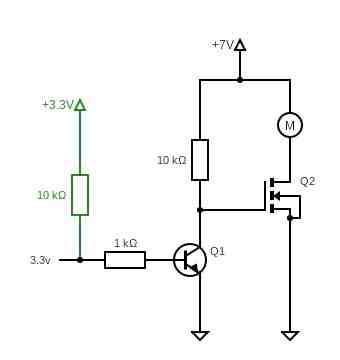
However, this solution was really complex for the problem that was addressing. The water pump just draws 50mA of current at full power, so it can be controlled with just a single BJT transistor, leaving us a pretty simple circuit.

Part 4: Aim and ... shoot!
The last part of the truck is the building of the tower that controls the direction of the water splash. The tower is build around two servos: one for vertical and the second one for horizontal aiming. There are two main problems here, the servo calibration, and the aiming.
For the servo calibration, we have to take into account that, since these are cheap servos, they do not follow the standard protocol exactly, that is why my servo library allows for a simple calibration. This calibration methods allow to set the value of the PWM for 0, 90 and 180 degrees.
So, once the PWM signal was configured for the 20ms period, I did a testbench in order to get the values of microseconds that makes the servos go from 0 to 180 degrees.

Then with these values, the servo library has two methods to move them: one with degrees as input, and another one with microseconds. If they are calibrated, the first one is recomended. Also, limits for the movement of the servos can be configured, therefore if the servo is commanded to move further the limit, the servo will stop in the limit.
Until now, I can aim the tower, however the aiming was not related to the information received by the "guidance system", in order to fix the aiming. First I have to do some experiments to calculate the relation between the angle of the vertical servo, and the distance to where the water hits the ground.
The results were as follow:
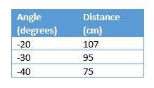
With this values, we can now interpolate, with a simple linear interpolation, the angle of the vertical servo. So finally, we can calculate the orientation of the vertical and horizontal servos, based on the distance and angle to the target!
All together
We have seen each part separately, but the fun part comes when they get connected together. The next image represent how all the items are conected, the voltages of each one, and all the interfaces needed.

The Embedded code
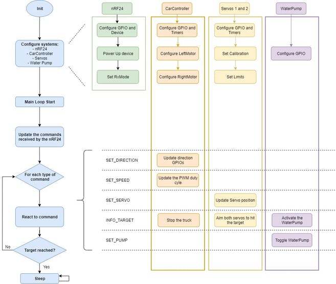
I tried to do the code as self-explanatory as possible, but the big picture would be:
- First we call all the initialization for each component. Each one has the Init/Config function in order to configure the GPIOs and internal registers (timers, ...)
- Then in the main loop I just get all the new commands from the nRF24L01 wifi device and update the commands. Then, only new commands are executed, each one in its component. For example, if a "SET_SERVO" arrives, in that loop the software will set the servo position and mark the command as "old", so it is not processed again. However, every command is stored until the next one arrives.
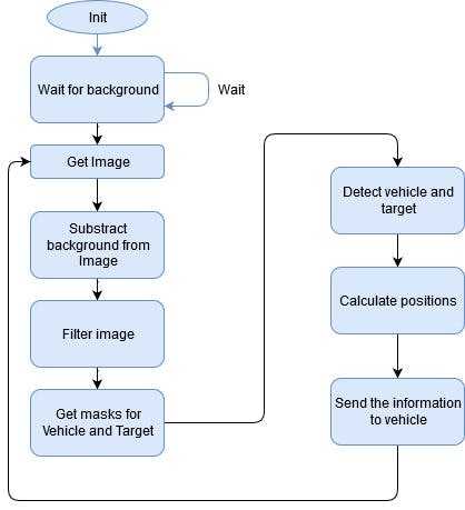
In the following picture we can see the full software flow. On the left column we have the entry point of the software, while the other 4 columns are the components of the project and what they do in each step of the main program.
The OpenCV Code
The folder 'openCV' of the project contains the code for the python and openCV. There we have 5 files:
- primerIntento.py it was a playground to learn how to start detecting things with openCV, so this is not mandatory for the project, and hence it is not clean nor optimized
- Calibration.py: is the file that handles the calibration process of the Camera, it only has to be run once.
- ApagaFuegos.py is the main file of the software. This piece of software initialize the camera, the detection algorithm and execute it in the main loop
- Comms.py contains all the code to initialize the serial, compose the data packets and send it to the Arduino with the nRF24
- Detector.py Has all the logic of the detection algorithm. It can work in three modes: Simple (which is the simplest one and now it try to go to the target using only 2 elements), the tester (which is used to get the HSV filter in realtime) and the normal mode (which is the one used in the AFT)
How to use it
In order to replicate this project the following steps shall be followed:
- Assemble the hardware following the previous notes
- Flash the Embedded AdaCore source in the stm32F407
- Flash the Arduino Code to send data over the WiFi
- Adapt the openCV Comms script to open the correct Serial port.
- Setup the webcam and connect to the PC.
- Launch the "ApagaFuegos" in the openCV folder
- Once the scenario is clear, press "b" to take a picture of the background
- Add the truck and the fire to the scenario
- Press "m" to activate the movement in the Truck
- Wait and enjoy! :D
Conclusion and future
As we can see in the video, the truck work as expected, and actually moves to the target and aim to it. However, as this is a prototype is has a strong contrains in the enviroment, due to the openCV algorithm, which is where this project is highly improbable.