Make with Ada 2020: CHIP-8 Interpreter
by Juliana Silva –
Laurent Zhu's and Damien Grisonnet's project won a finalist prize in the Make with Ada 2019/20 competition. This project was originally posted on Hackster.io here. For those interested in participating in the 2020/21 competition, registration is now open and project submissions will be accepted until Jan 31st 2021, register here.
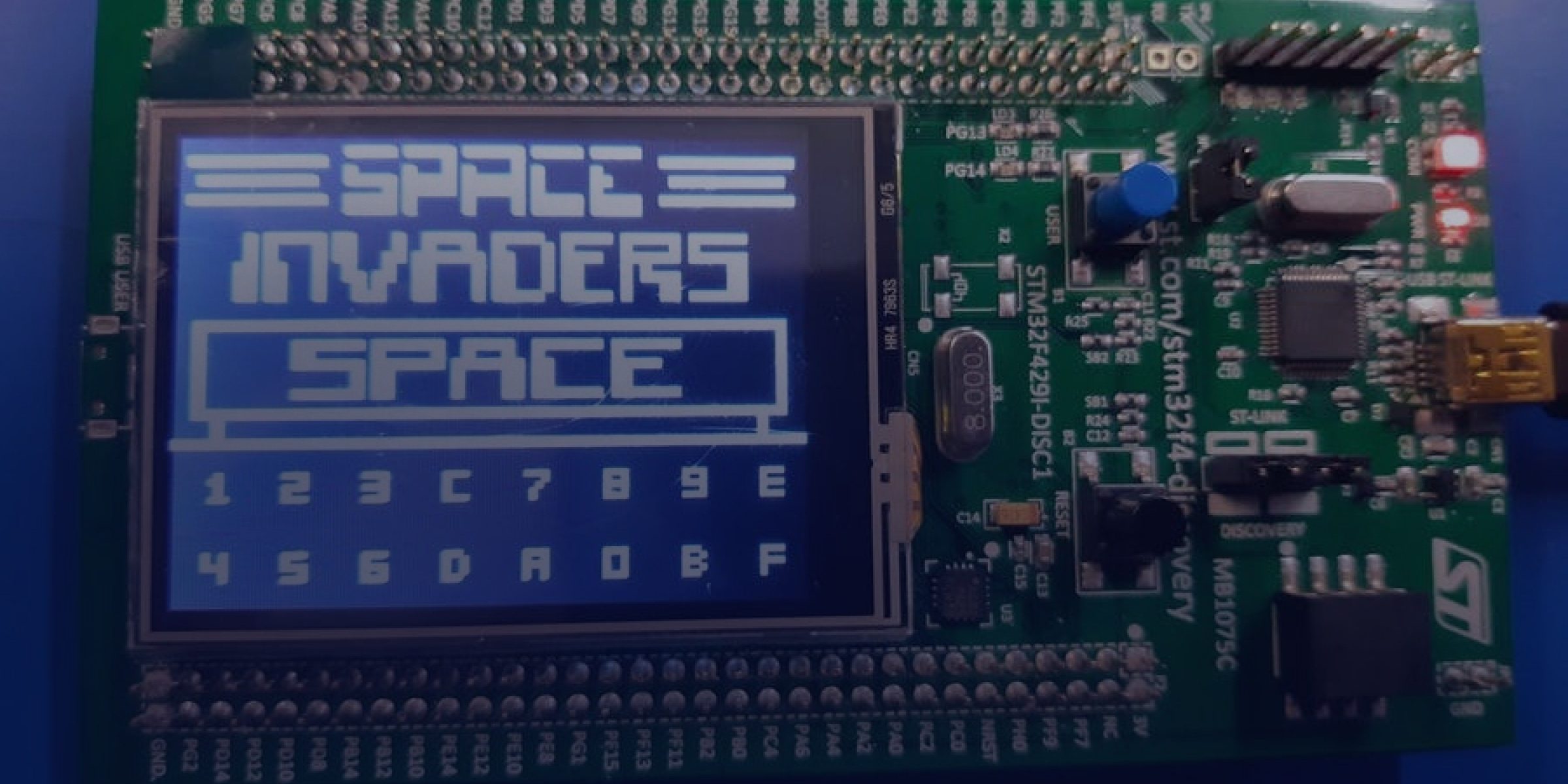
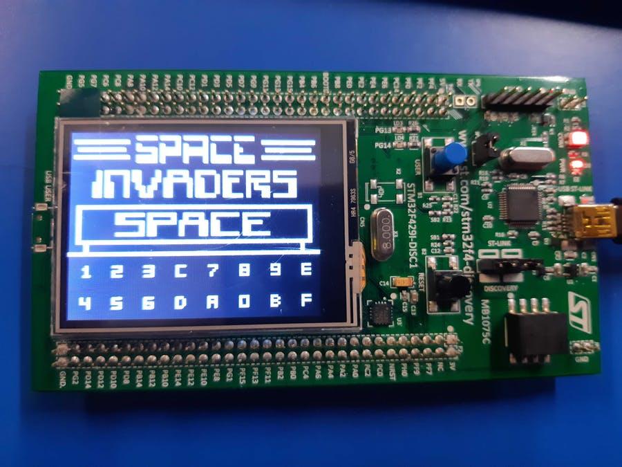
CHIP-8 language interpreter for STM32F429 Discovery board
Story
Motivations
This project was accomplished for the EPITA Ada courses and the Make With Ada contest.
Originally this project was supposed to be a GBA emulator. However, instead of implementing one from scratch in ADA we wanted to port an existing one on the STM32F429 Discovery and write bindings in ADA. But, while trying to port the emulator we noticed that there was not much to do in ADA and that the project would be mostly written in C instead of ADA. We thought that it was a pity since we were supposed to do a project in ADA. Then, we decided to switch to another project that would allow us to write more ADA. We could have written our own GBA emulator in ADA but it was too big of a challenge to write one on time for the challenge. Thus, we decided to write this CHIP-8 emulator instead which involves the same coding challenges as the GBA one but it is way faster to implement.
CHIP-8
The first step of the project was to understand how the emulator is working:
Memory
Memory size of 4K with the first 512 bytes of the memory space reserved for the CHIP-8 interpreter. It is common to use this reserved space to store font data.
Registers
CHIP-8 has 16 8-bit data registers named V0 to VF.
Stack
The stack is only used to store return addresses when subroutines are called. In modern implementations stacks can store up to 16 elements.
Timers
CHIP-8 has two timers. They both count down at 60 hertz, until they reach 0.
- Delay timer: This timer is intended to be used for timing the events of games. Its value can be set and read.
- Sound timer: This timer is used for sound effects. When its value is nonzero, a beeping sound is made.
Inputs
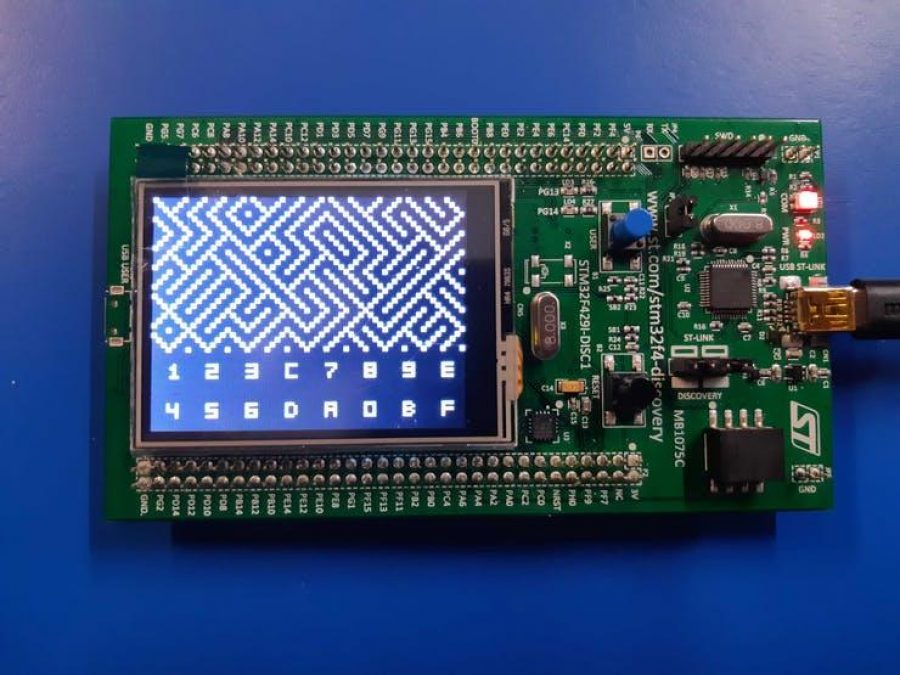
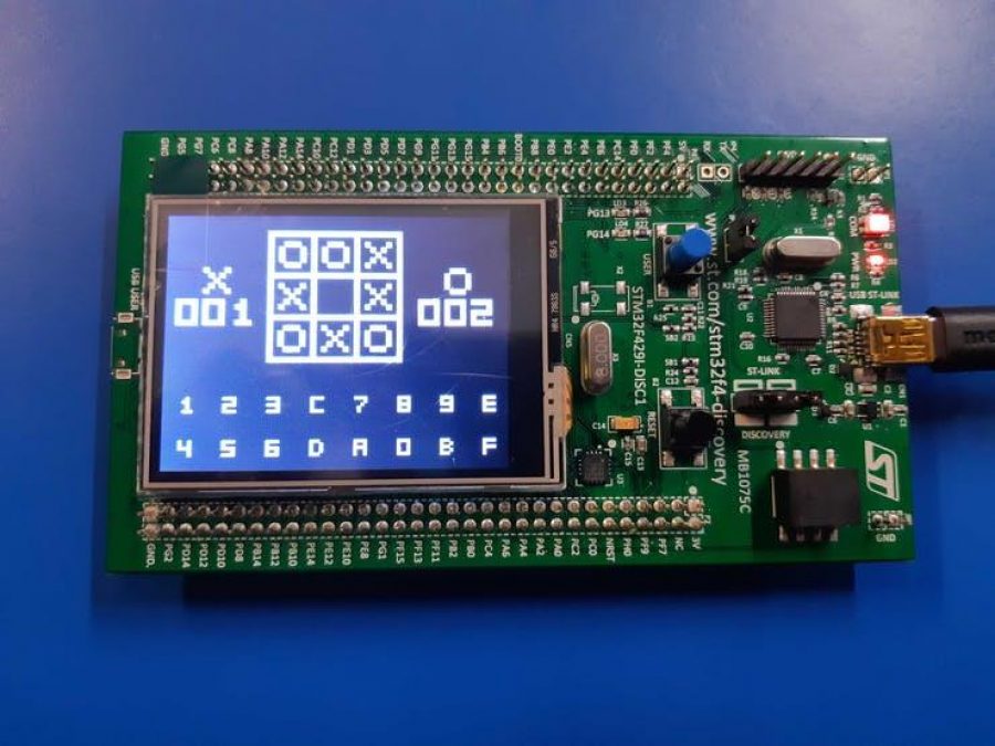
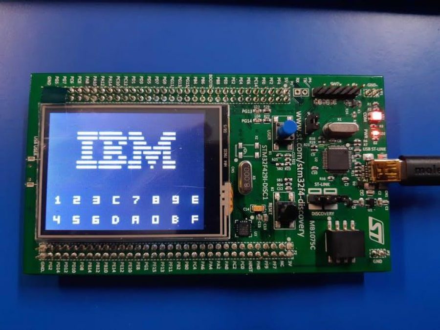
Input is done with a hex keyboard that has 16 keys ranging 0 to F.
This keyboard is displayed on the bottom part of the screen of the STM32F429 Discovery.
Graphics
Original CHIP-8 Display resolution is 64×32 pixels, and color is monochrome. Graphics are drawn to the screen solely by drawing sprites, which are 8 pixels wide and may be from 1 to 15 pixels in height. Sprite pixels are XOR'd with corresponding screen pixels. In other words, sprite pixels that are set flip the color of the corresponding screen pixel, while unset sprite pixels do nothing. The carry flag (VF) is set to 1 if any screen pixels are flipped from set to unset when a sprite is drawn and set to 0 otherwise. This is used for collision detection.
Since the STM32F429 Discovery screen resolution is 320x240, the display of the ROM was scale 5 times to improve the user experience and to match the platform.
Sound
A beeping sound is supposed to be played when the value of the sound timer is nonzero. However, since the STM32F429 Discovery does not have any audio module, no sound are played.
Opcode Table
CHIP-8 has 35 opcodes, which are all two bytes long and stored big-endian.
CHIP-8 Interpreter
The different steps of the interpreter:
- The screen, the touch panel and the layers are initialized
- We draw the keyboard on the bottom of screen with the first layer, by using the CHIP-8 sprites. In order to do that, we iterate through all the existing keys and from their position in the font set table, we can draw it easily
- A ROM is loaded with the Load_Rom procedure. The ROMs are located in the file that we generate with a python script (
scripts/gen_rom.py). It generates all the Ada arrays from all the ROMs located in theroms/directory. - Then, we have our main loop:
Main Loop
- An opcode, consisting of 2 bytes, is fetched from the memory at the program counter position
- We call the right function to execute by looking at the 4 first bits of our opcode. Some instruction will not increment the program counter, some will increment it and some will skip the next instruction by incrementing 2 times more
- At the end of the loop we read the touch screen inputs and we update the list of pressed keys accordingly
Setup the project
git clone https://github.com/laurentzh/CHIP-8.git
cd CHIP-8
git clone --recursive https://github.com/AdaCore/Ada_Drivers_Library.git
source env.sh
python2 Ada_Drivers_Library/scripts/install_dependencies.py
Compile the project
gprbuild --target=arm-eabi -d -P chip8.gpr -XLCH=led -XRTS_Profile=ravenscar-sfp -XLOADER=ROM -XADL_BUILD_CHECKS=Disabled src/main.adb -largs -Wl,-Map=map.txtFlash the project
arm-eabi-objcopy -O binary objrelease/main objrelease/main.bin
st-flash --reset write objrelease/main.bin 0x8000000
Add a ROM
cp $ROM roms/
./scripts/gen_rom.py roms/ src/roms.ads
Change ROM
We encountered a few memory problems with the implementation of the menu. So, in order to choose the ROM, you need to change the argument of the call to Load_Rom in the main.adb file.
Examples
Simple ROM that does not require user interaction:
Demonstrations
BLINKY (Pacman-like) - CHIP-8 Interpreter on STM32F429
TETRIS - CHIP-8 Interpreter on STM32F429