Make with Ada 2017: Brushless DC Motor Controller
by Jonas Attertun –
Not long after my first experience with the Ada programming language I got to know about the Make With Ada 2017 contest. And, just as it seemed, it turned out to be a great way to get a little bit deeper into the language I had just started to learn
The ada-motorcontrol project involves the design of a BLDC motor controller software platform written in Ada. These types of applications often need to be run fast and the core control software is often tightly connected to the microcontroller peripherals. Coming from an embedded systems perspective with C as the reference language, the initial concerns were if an implementation in Ada actually could meet these requirements.
It turned out, on the contrary, that Ada is very capable considering both these requirements. In particular, accessing peripherals on the STM32 with help of the Ada_Drivers_Library really made using the hardware related operations even easier than using the HAL written in C by ST.
Throughout the project I found uses for many of Ada’s features. For example, the representation clause feature made it simple to extract data from received (and to put together the transmit) serial byte streams. Moreover, contract based programming and object oriented concepts such as abstracts and generics provided means to design clean and easy to use interfaces, and a well organized project.
One of the objectives of the project was to provide a software platform to help developing various motor control applications, with the core functionality not being dependent on some particular hardware. Currently however it only supports a custom inverter board, since unfortunately I found that the HAL provided in Ada_Drivers_Library was not comprehensive enough to support all the peripheral features used. But the software is organized such as to keep driver dependent code separated. To put this to test, I welcome contributions to add support for other inverter boards. A good start would be the popular VESC-board.
Ada Motor Controller Project Log:
Motivation
The recent advances in electric drives technologies (batteries, motors and power electronics) has led to increasingly higher output power per cost, and power density. This in turn has increased the performance of existing motor control applications, but also enabled some new - many of them are popular projects amongst diyers and makers, e.g. electric bike, electric skateboard, hoverboard, segway etc.
On a hobby-level, the safety aspects related to these is mostly ignored. Professional development of similar applications, however, normally need to fulfill some domain specific standards putting requirements on for example the development process, coding conventions and verification methods. For example, the motor controller of an electric vehicle would need to be developed in accordance to ISO 26262, and if the C language is used, MISRA-C, which defines a set of programming guidelines that aims to prevent unsafe usage of the C language features.
Since the Ada programming language has been designed specifically for safety critical applications, it could be a good alternative to C for implementing safe motor controllers used in e.g. electric vehicle applications. For a comparison of MISRA-C and Ada/SPARK, see this report. Although Ada is an alternative for achieving functional safety, during prototyping it is not uncommon that a mistake leads to destroyed hardware (burned motor or power electronics). Been there, done that! The stricter compiler of Ada could prevent such accidents.
Moreover, while Ada is not a particularly "new" language, it includes more features that would be expected by a modern language, than is provided by C. For example, types defined with a specified range, allowing value range checks already during compile time, and built-in multitasking features. Ada also supports modularization very well, allowing e.g. easy integration of new control interfaces - which is probably the most likely change needed when using the controller for a new application.
This project should consist of and fulfill:
- Core software for controlling brushless DC motors, mainly aimed at hobbyists and makers.
- Support both sensored and sensorless operation.
- Open source software (and hardware).
- Implementation in Ada on top of the Ravenscar runtime for the stm32f4xx.
- Should not be too difficult to port to another microcontroller.
And specifically, for those wanting to learn the details of motor control, or extend with extra features:
- Provide a basic, clean and readable implementation.
- Short but helpful documentation.
- Meaningful and flexible logging.
- Easy to add new control interfaces (e.g. CAN, ADC, Bluetooth, whatever).
Hardware
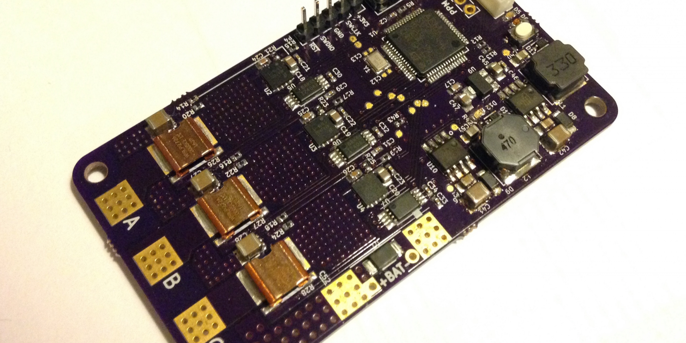
The board that will be used for this project is a custom board that I previously designed with the intent to get some hands-on knowledge in motor control. It is completely open source and all project files can be found on GitHub.
- Microcontroller STM32F446, ARM Cortex-M4, 180 MHz, FPU
- Power MOSFETs 60 V
- Inline phase current sensing
- PWM/PPM control input
- Position sensor input as either hall or quadrature encoder
- Motor and board temp sensor (NTC)
- Expansion header for UART/ADC/DAC/SPI/I2C/CAN
It can handle power ranges in the order of what is required by an electric skateboard or electric bike, depending on the used battery voltage and cooling.
There are other inverter boards with similar specifications. One very popular is the VESC by Benjamin Vedder. It is probably not that difficult to port this project to work on that board as well.

Rough project plan
I thought it would be appropriate to write down a few bullets of what needs to be done. The list will probably grow...
- Create a port of the Ravenscar runtime to the stm32f446 target on the custom board
- Add stm32f446 as a device in the Ada Drivers Library
- Get some sort of hello world application running to show that stuff works
- Investigate and experiment with interrupt handling with regards to overhead
- Create initialization code for all used mcu peripherals
- Sketch the overall software architecture and define interfaces
- Implementation
- Documentation...
Support for the STM32F446
The microprocessor that will be used for this project is the STM32F446. In the current version of the Ada Drivers Library and the available Ravenscar embedded runtimes, there is no explicit support for this device. Fortunately, it is very similar to other processors in the stm32f4-family, so adding support for stm32f446 was not very difficult once I understood the structure of the repositories. I forked these and added them as submodules in this project's repo.
Compared to the Ravenscar runtimes used by the discovery-boards, there are differences in external oscillator frequency, available interrupt vectors and memory sizes. Otherwise they are basically the same.
An important tool needed to create the new driver and runtime variants is svd2ada. It generates device specification and body files in ada based on an svd file (basically xml) that describes what peripherals exist, how their registers look like, their address', existing interrupts, and stuff like that. It was easy to use, but a little bit confusing how flags/switches should be set when generating driver and runtime files. After some trail and error I think I got it right. I created a Makefile for generating all these file with correct switches.
I could not find an svd-file for the stm32f446 directly from ST, but found one on the internet. It was not perfect though. Some of the source code that uses the generated data types seems to make assumptions on the structure of these types. Depending on how the svd file looks, svd2ada may or may not generate them in the expected way. There were also other missing and incorrect data in the svd file, so I had to manually correct these. There are probably additional issues that I have not found yet...
It is alive!
I made a very simple application consisting of a task that is periodically delayed and toggles the two leds on the board each time the task resumes. The leds toggles with the expected period, so the oscillator seems to be initialized correctly.
Next up I need to map the different mcu pins to the corresponding hardware functionality and try to initialize the needed peripherals correctly.
The control algorithm and its use of peripherals
There are several methods of controlling brushless motors, each with a specific use case. As a first approach I will implement sensored FOC, where the user requests a current value (or torque value).
To simplify, this method can be divided into the following steps, repeated each PWM period (typically around 20 kHz):
- Sample the phase currents
- Transform the values into a rotor fixed reference frame
- Based on the requested current, calculate a new set of phase voltages
- Transform back to the stator's reference frame
- Calculate PWM duty cycles as to create the calculated phase voltages
Fortunately, the peripherals of the stm32f446 has a lot of features that makes this easier to implement. For example, it is possible to trigger the ADC directly from the timers that drives the PWM. This way the sampling will automatically be synchronized with the PWM cycle. Step 1 above can thus be started immediately as the ADC triggers the corresponding conversion-complete-interrupt. In fact, many existing implementations perform all the steps 1-to-6 completely within an ISR. The reason for this is simply to reduce any unnecessary overhead since the performed calculations is somewhat lengthy. The requested current is passed to the ISR via global variables.
I would like to do this the traditional way, i.e. to spend as little time as possible in the ISR and trigger a separate Task to perform all calculations. The sampled current values and the requested current shall be passed via Protected Objects. All this will of course create more overhead. Maybe too much? Need to be investigated.
PWM and ADC is up and running
I have spent some time configuring the PWM and ADC peripherals using the Ada Drivers Library. All in all it went well, but I had to do some smaller changes to the drivers to make it possible to configure the way I wanted.
- PWM is complementary output, center aligned with frequency of 20 kHz
- PWM channels 1 to 3 generates the phase voltages
- PWM channel 4 is used to trigger the ADC, this way it is possible to set where over the PWM period the sampling should occur
- By default the sampling occurs in the middle of the positive waveform (V7)
- The three ADC's are configured to Triple Multi Mode, meaning they are synchronized such that each sampled phase quantity is sampled at the same time.
- Phase currents and voltages a,b,c are mapped to the injected conversions, triggered by the PWM channel 4
- Board temperature and bus voltage is mapped to the regular conversions triggered by a timer at 14 kHz
- Regular conversions are moved to a volatile array using DMA automatically after the conversions complete
- ADC create an interrupt after the injected conversions are complete
The drivers always assumed that the PWM outputs are mapped to a certain GPIO, so in order to configure the trigger channel I had to add a new procedure to the drivers. Also, the Scan Mode of the ADCs where not set up correctly for my configuration, and the config of injected sequence order was simply incorrect. I will send a pull request to get these changes merged with the master branch.
Interrupt overhead/latency
As was described in previous posts the structure used for the interrupt handling is to spend minimum time in the interrupt context and to signal an awaiting task to perform the calculations, which executes at a software priority level with interrupts fully enabled. The alternative method is to place all code in the interrupt context.
This Ada Gem and its following part describes two different approaches for doing this type of task synchronization. Both use a protected procedure as the interrupt handler but signals the awaiting task in different ways. The first uses an entry barrier and the second a Suspension Object. The idiom using the entry barrier has the advantage that it can pass data as an integrated part of the signaling, while the Suspension Object behaves more like a binary semaphore.
For the ADC conversion complete interrupt, I tested both methods. The protected procedure used as the ISR read the converted values consisting of six uint16. For the entry barrier method these where passed to the task using an out-parameter. When using the second method the task needed to collect the sample data using a separate function in the protected object.
Overhead in this context I define as the time from that the ADC generates the interrupt, to the time the event triggered task starts running. This includes, first, an isr-wrapper that is a part of the runtime which then calls the installed protected procedure, and second, the execution time of the protected procedure which reads the sampled data, and finally, the signaling to the awaiting task.
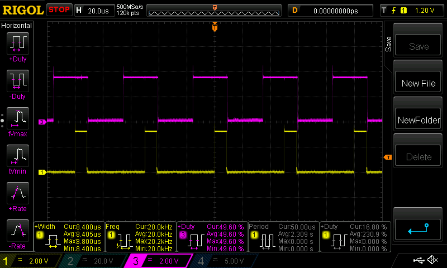
I measured an approximation of the overhead by setting a pin high directly in the beginning of the protected procedure and then low by the waiting task directly when waking up after the signaling. For the Suspension Object case the pin was set low after the read data function call, i.e. for both cases when the sampled data was copied to the task. The code was compiled with the -O3 flag.
The first idiom resulted in an overhead of ~8.4 us, and the second ~10 us. This should be compared to the period of the PWM which at 20 kHz is 50 us. Obviously the overhead is not negligible, so I might consider using the more common approach for motor control applications of having the current control algorithm in the interrupt context instead. However, until the execution time of the algorithm is known, the entry barrier method will be assumed...
Note: "Overhead" might be the wrong term since I don't know if during the time measured the cpu was really busy. Otherwise it should be called latency I think...
Reference frames
A key benefit of the FOC algorithm is that the actual control is performed in a reference frame that is fixed to the rotor. This way the sinusoidal three phase currents, as seen in the stator's reference frame, will instead be represented as two DC values, assuming steady state operation. The transforms used (Clarke and Park) requires that the angle between the rotor and stator is known. As a first step I am using a quadrature encoder since that provides a very precise measurement and very low overhead due to the hardware support of the stm32.
Three types has been defined, each representing a particular reference frame: Abc, Alfa_Beta and Dq. Using the transforms above one can simply write:
declare
   Iabc  : Abc;  --  Measured current (stator ref)
   Idq   : Dq;   --  Measured current (rotor ref)
   Vdq   : Dq;   --  Calculated output voltage (rotor ref)
   Vabc  : Abc;  --  Calculated output voltage (stator ref)
   Angle : constant Float := ...;
begin
   Idq := Iabc.Clarke.Park(Angle);

   --  Do the control...

   Vabc := Vdq.Park_Inv(Angle).Clarke_Inv;
end;
Note that Park and Park_Inv both use the same angle. To be precise, they
both use Sin(Angle) and Cos(Angle). Now, at first, I simply implemented
these by letting each transform calculate Sin and Cos locally. Of
course, that is a waste for this particular application. Instead, I
defined an angle object that when created also computed Sin and Cos of
the angle, and added versions of the transforms to use these
"ahead-computed" values instead.
declare
   --  Same...

   Angle : constant Angle_Obj := Compose (Angle_Rad);
   --  Calculates Sin and Cos
begin
   Idq := Iabc.Clarke.Park(Angle);

   --  Do the control...

   Vabc := Vdq.Park_Inv(Angle).Clarke_Inv;
end;
This reduced the execution time somewhat (not as much as I thought, though), since the trigonometric functions are the heavy part. Using lookup table based versions instead of the ones provided by Ada.Numerics might be even faster...
It spins!
The main structure of the current controller is now in place. When a button on the board is pressed the sensor is aligned to the rotor by forcing the rotor to a known angle. Currently, the requested q-current is set by a potentiometer.
As of now, it is definitely not tuned properly, but it at least it shows that the general algorithm is working as intended.
In order to make this project easier to develop on, both for myself and any other users, I need to add some logging and tuning capabilities. This should allow a user to change and/or log variables in the application (e.g. control parameters) while the controller is running. I have written a tool for doing this (over serial) before, but then in C. It would be interesting to rewrite it in Ada.
Contract Based Programming
So far, I have not used this feature much. But when writing code for the logging functionality I ran into a good fit for it.
I am using Consistent Overhead Byte Stuffing (COBS) to encode the data sent over uart. This encoding results in unambiguous packet framing regardless of packet content, thus making it easy for receiving applications to recover from malformed packets. The packets are separated by a delimiter (value 0 in this case), making it easy to synchronize the receiving parser. The encoding ensures that the encoded packet itself does not contain the delimiter value.
A good feature of COBS is that given that the raw data length is less than 254, then the overhead due to the encoding is always exactly one byte. I could of course simply write this fact as a comment to the encode/decode functions, allowing the user to make this assumption in order to simplify their code. A better way could be to write this condition as contracts.
Data_Length_Max : constant Buffer_Index := 253;

   function COBS_Encode (Input : access Data)
                         return Data
   with
      Pre => Input'Length <= Data_Length_Max,
      Post => (if Input'Length > 0 then
                  COBS_Encode'Result'Length = Input'Length + 1
               else
                  Input'Length = COBS_Encode'Result'Length);

   function COBS_Decode (Encoded_Data : access Data)
                         return Data
   with
      Pre => Encoded_Data'Length <= Data_Length_Max + 1,
      Post => (if Encoded_Data'Length > 0 then
                  COBS_Decode'Result'Length = Encoded_Data'Length - 1
               else
                  Encoded_Data'Length = COBS_Decode'Result'Length);
Logging and Tuning
I just got the logging and tuning feature working. It is an Ada-implementation using the protocol as used by a previous project of mine, Calmeas. It enables the user to log and change the value of variables in the application, in real-time. This is very helpful when developing systems where the debugger does not have a feature of reading and writing to memory while the target is running.
The data is sent and received over uart, encoded by COBS. The interfaces of the uart and cobs packages implements an abstract stream type, meaning it is very simple to change the uart to some other media, and that e.g. cobs can be skipped if wanted.
Example
The user can simply do the following in order to get the variable V_Bus_Log loggable and/or tunable:
V_Bus_Log  : aliased Voltage_V;
...
Calmeas.Add (Symbol      => V_Bus_Log'Access,
             Name        => "V_Bus",
             Description => "Bus Voltage [V]");
It works for (un)signed integers of size 8, 16 and 32 bits, and for floats.
After adding a few variables, and connecting the target to the gui:

As an example, this could be used to tune the current controller gains:
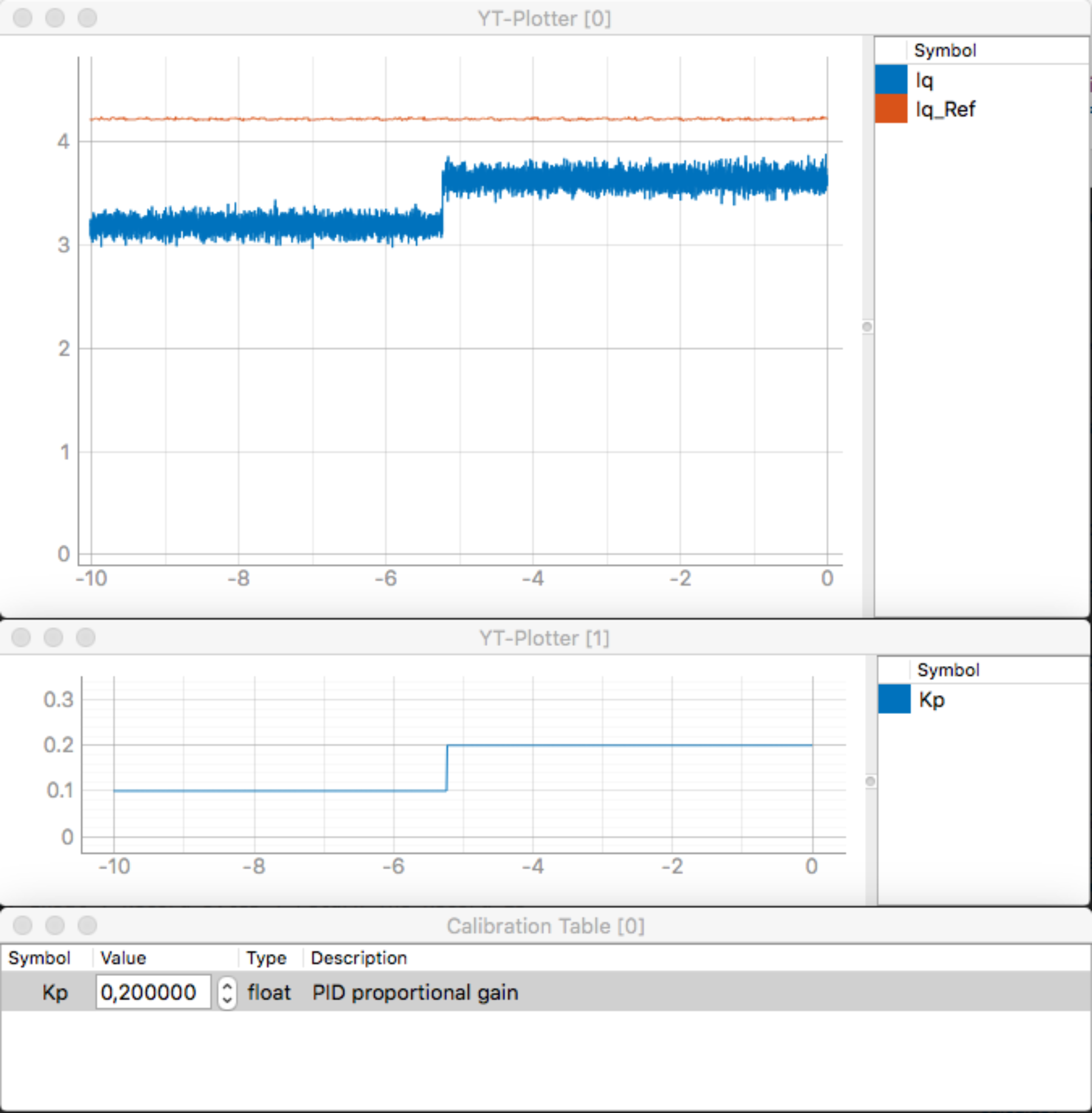
As expected, the actual current comes closer to the reference as the gain increases
As of now, the tuning is not done in a "safe" way. The writing to added symbols is done by the separate task named Logger, simply by doing unchecked writes to the address of the added symbol, one byte at a time. At the same time the application is reading the symbol's value from another task with higher prio. The optimal way would be to pass the value through a protected type, but since the tuning is mostly for debugging purposes, I will make it the proper way later on...
Note that the host GUI is not written in Ada (but Python), and is not itself a part of this project.
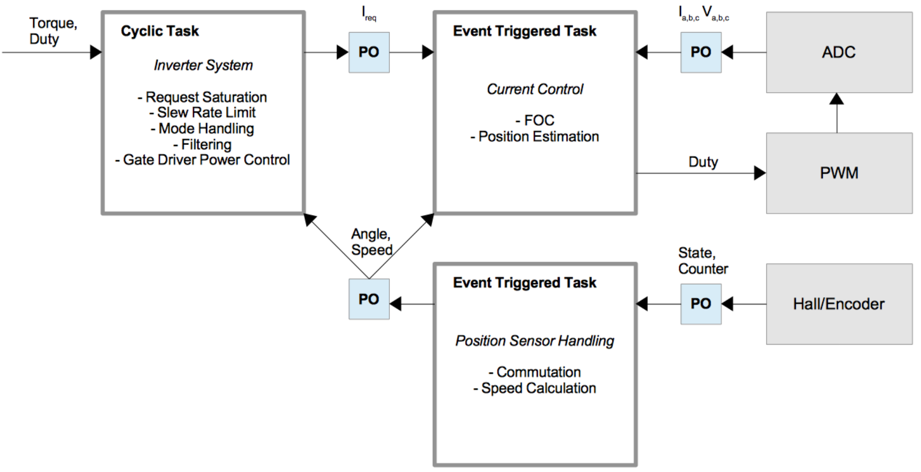
Architecture overview
Here is a figure showing an overview of the software:
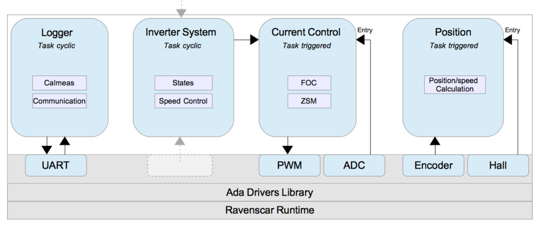
Summary
This project involves the design of a software platform that provides a good basis when developing motor controllers for brushless motors. It consist of a basic but clean and readable implementation of a sensored field oriented control algorithm. Included is a logging feature that will simplify development and allows users to visualize what is happening. The project shows that Ada successfully can be used for a bare-metal project that requires fast execution.
The design is, thanks to Ada's many nice features, much easier to understand compared to a lot of the other C-implementations out there, where, as a worst case, everything is done in a single ISR. The combination of increased design readability and the strictness of Ada makes the resulting software safer and simplifies further collaborative development and reuse.
Some highlights of what has been done:
- Porting of the Ravenscar profiles to a custom board using the STM32F446
- Adding support for the STM32F446 to Ada_Drivers_Library project
- Adding some functionality to Ada_Drivers_Library in order to fully use all peripheral features
- Fixing a bug in Ada_Drivers_Library related to a bit more advanced ADC usage
- Written HAL-isch packages so that it is easy to port to another device than STM32
- Written a communication package and defined interfaces in order to make it easier to add control inputs.
- Written a logging package that allows the developer to debug, log and tune the application in real-time.
- Implemented a basic controller using sensored field oriented control
- Well documented specifications with a generated html version
Future plans:
- Add hall sensor support and 6-step block commutation
- Add sensorless operation
- Add CAN support (the pcb has currently no transceiver, though)
- SPARK proving
- Write some additional examples showing how to use the interfaces.
- Port the software to the popular VESC-board.